Tiếng Việt
Technical Support
PowerFlex PWM AC Drives: SCR/Diode and IGBT Test

Summary
PowerFlex PWM AC Drives: SCR/Diode and IGBT Test
Question
- How are the forward and reverse biased SCR/diode tests performed on the major power components of an AC drive?
- How should a diode test be performed to check the health of the SCRs or IGBTs on a AC drive?
- Why does my diode static check show OL for both the forward bias and reverse bias readings of the input section and output section of the drive in regard to the DC- terminal? [See Note: in the Answer.]
- Why I am not getting any display on my drive and what checks can be done to see if power structure of drive is ok?
- How can the power structure be checked on an AC drive for the purposes of troubleshooting faults related one of the following?
- Open/blown line fuses
- Line loss
- Bus under voltage
- Shorted output
Environment
- 20A PowerFlex 70
- 20B PowerFlex 700
- 20C PowerFlex 700H
- 20D PowerFlex 700S
- 20F PowerFlex 753
- 20G PowerFlex 755
- 20G PowerFlex 755T
- 20J PowerFlex 755TM Bus Supply
- 22A PowerFlex 4
- 22B PowerFlex 40
- 22C PowerFlex 400
- 22D PowerFlex 40P
- 22F PowerFlex 4M
- 25A PowerFlex 523
- 25B PowerFlex 525
- 25C PowerFlex 527
Answer
The PowerFlex drives will have different preliminary steps and cautions depending on family and size. Refer to their respective service manuals. Below is a basic overview of a procedure. This procedure is strictly a guideline.
- Remove power from the drive and wait for the drive to completely power down.
- Open drive enclosure door or remove the cover(s) from the drive.
- Verify DC bus is near 0 VDC by measuring from DC+ to DC- terminals (if your drive has these terminals).
- Remove primary fuses (if applicable).
- Disconnect motor leads (U, V, and W) at the drive’s terminal block.
- Disconnect line side leads (R, S, and T) at the drive’s terminal block.
- It may be necessary to insert insulating material between U, V, and W to ensure these terminals do not make contact to receive accurate results.
- If the drive is a PowerFlex 755T frame 7 or higher, roll out the power module that is being
The power structure of an AC drive consists of diodes or SCRs on the input and IGBTs on the output.
Diodes will go into conduction and exhibit a voltage drop between 0.3 V – 0.7 V when forward biased, and read OL (open circuit) when reverse biased. SCRs will read OL in forward or reverse bias. IGBTs can be tested by measuring the flyback diode that is reverse biased across the IGBT. Therefore, all readings described below are done with a digital multi meter in diode test mode.
Generally, drives under 50 hp will have diode inputs. Larger drives may have SCR inputs, or an input comprised of 3 diodes and 3 SCRs which results in 3 OLs and 3 diode voltage drops.
The following schematics shows the basic structure of a drive and its terminals.
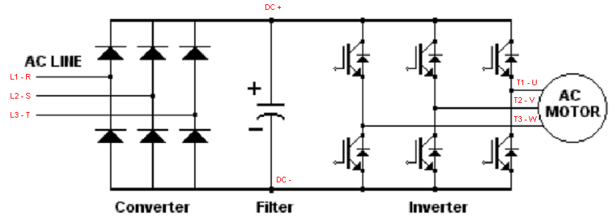
Depending on the PowerFlex and frame size, the components that make up the converter will differ and thus have different measurements. For further explanation or clarification on your specific drive product and what the results of these tests should be, contact Technical Support. Be sure to have the complete catalog number of the drive.
6 Diode Bridge Rectifier
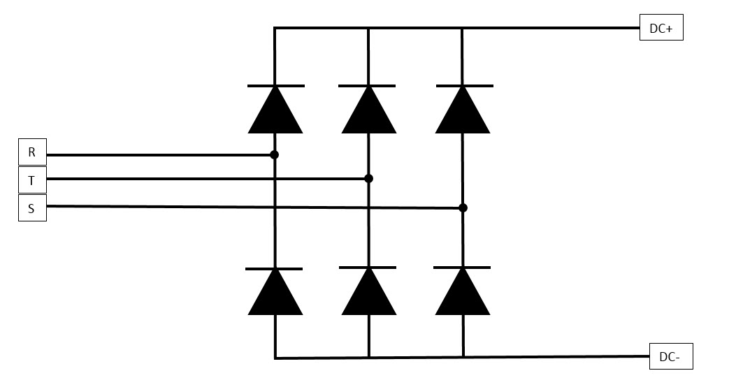
The following drives have this type of converter:
- PowerFlex 4-series
- PowerFlex 520-series
- PowerFlex 70
- PowerFlex 700 (Frames 1-4)
- PowerFlex 700S (Frames 1-4)
- PowerFlex 750 (Frames 1-4)
6 SCR Bridge Rectifier
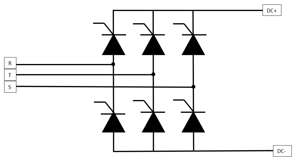
The following drives have this type of converter:
- PowerFlex 700 HIHP
- PowerFlex 700 (Frames 5 and higher)
This type of power structure cannot be tested for forward biasing without a gate pulse. You can only check to see if the SCR is shorted. You should read open on all measurements forward/reversed biased.
3 Diode/3 SCR Bridge Rectifier
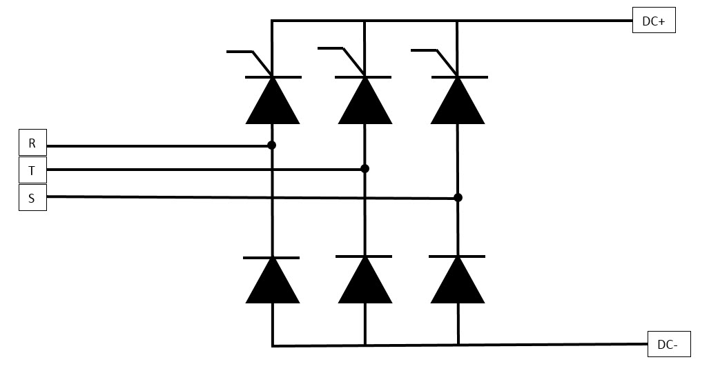
The following drives have this type of converter:
- PowerFlex 700S (Frames 5, 6, 9, 10, 11)
- PowerFlex 755 HIHP (Frames 8-10)
3 Diode/3 SCR Bridge Rectifier with Precharge Diodes
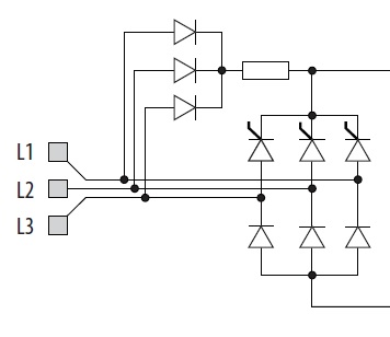
The following drives have this type of converter:
- PowerFlex 750 (Frames 5-7)
Active Front End
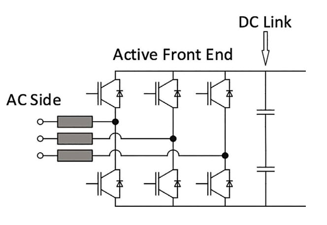
The following drives have this type of converter:
- PowerFlex 755TR (frame 7 and higher)
- PowerFlex 755TL (frame 7 and higher)
- PowerFlex 755TM (Bus Supply) (frame 7 and higher)
PowerFlex 755T frame 5 and 6 drives have a precharge resistor on the R phase (see image below). This resistor will affect the measurements.
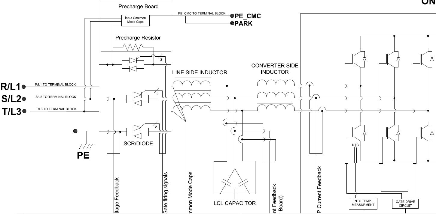
The following drives have this type of converter:
- PowerFlex 755TR (frame 5 and 6)
- PowerFlex 755TL (frame 5 and 6)
- PowerFlex 755TM (Bus Supply) (frame 5 and 6)
Doing the measurement verification – Converter/Rectifier
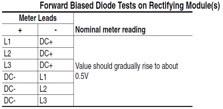
Set the digital multimeter to “diode check” and follow the table below for forward biased tests. Before conducting the test, make sure all of the power terminals have (R, S, T, DC+, DC-, U, V and W) have all been tightened down. Failure to do this may result in a incorrect OL reading. The voltage readings will differ between PowerFlex families and sizes. Look for open or short circuits, depending upon the test. If the drive has a problem related to the power structure, then typically one reading will be noticeably different from the others. The tables below have diode or diode/SCR converters. Complete the tests according to the drive family and frame sizes classified above. Contact Technical Support if you are unsure of your drive’s power structure.
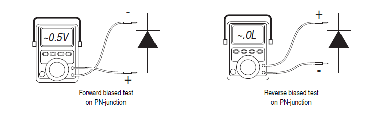
Perform the forward biased measurements following the instructions in one of the tables below.
Diode Converter and 3 Diode/3 SCR Bridge Rectifier with Precharge Diodes
Diode/SCR Converter
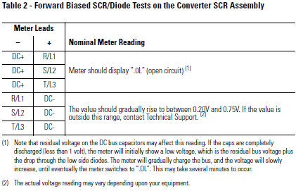
Note that an OL reading may not appear but rather a low voltage.
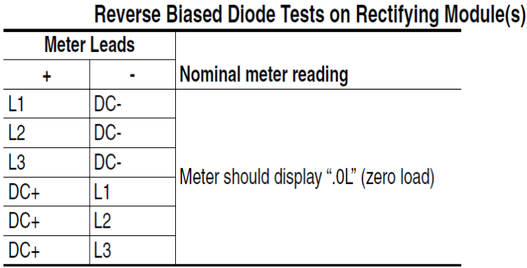
Repeat this procedure for the reverse biased tests following one of the tables below.
Diode Converter and 3 Diode/3 SCR Bridge Rectifier with Precharge Diodes
Diode/SCR Converter
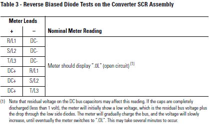
If any of these tests show a short (0.0V) try to find the cause of the short or replace the drive or converter section. If measurements are odd but not shorts, attempt to find cause or try a different meter. Depending on the readings, try applying power to see if anything is wrong or contact Tech Support.
Doing the measurement verification – Inverter IGBT Assembly
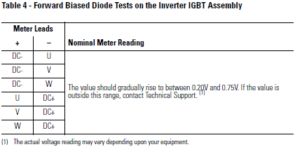
Repeat the procedure for the forward biased tests for the inverter IGBT assembly following the table below. Again, the voltage readings will differ between drive families and sizes; look for consistency. Use the last two tables for PowerFlex 755T frame 5 and 6 drives.
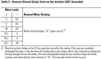
Repeat the procedure for the reverse biased tests of the IGBT’s following the table below:
Forward Biased Diode Test on IGBT Assembly (Converter PowerFlex 755T frames 5 and 6)
| Meter Leads | Nominal Meter Reading | |
| + | – | |
| -DC | R/L1 | 0.35 |
| -DC | S/L2 | 0.8 |
| -DC | T/L3 | 0.8 |
| R/L1 | +DC | 0.35 |
| S/L2 | +DC | OL |
| T/L3 | +DC | OL |
Reverse Biased Diode Test on IGBT Assembly (Converter PowerFlex 755T Frames 5 and 6
| Meter Leads | Nominal Meter Reading | |
| + | – | |
| R/L1 | -DC | OL |
| S/L2 | -DC | OL |
| T/L3 | -DC | OL |
| +DC | R/L1 | OL |
| +DC | S/L2 | OL |
| +DC | T/L3 | OL |
If any of these tests show a short (0.0V) try to find the cause of the short or replace the drive or converter section (smaller frame sizes can usually not have the converter replaced alone).
If measurements are odd but not shorts, attempt to find cause or try a different meter.
Note: Reverse biased diode tests on the IGBT can result in readings other than 0.0V (or close to 0) or OL. The readings can vary widely depending on the meter used and the amount of charge on the batteries in the meter. To ensure a 0.0V or OL reading, the motor and capacitor bank need to be disconnected from the drive.
If further assistance is required in troubleshooting or replacement contact Tech Support at 1-440-646-3434.
For PowerFlex 755TS drives, reference QA66542-PowerFlex 755TS Forward and Reverse Bias Check Frame 1-7
Source: Rockwell Automation’s Technote database.