Tiếng Việt
Technical Support
Micro800: Controlling PowerFlex Drives over Ethernet – CIP Messaging

Summary
Micro800: Controlling PowerFlex Drives over Ethernet – CIP messaging
Environment
- Micro800 controllers
- 25B PowerFlex 525 drives
Answer
To control a PowerFlex AC drive over EtherNet, use CIP Generic messages (MSG_CIPGENERIC). An example program routine is shown below.
Note: The User-Defined Function Block (UDFB) designed to control PowerFlex 4-Class, 520-Series, and 750-Series drives is available here:
Micro800 UDFB: EtherNet communications with PowerFlex 750-Series, 520-Series and 4-Class Drives.Refer to technote QA57091 – Micro800: Controlling PowerFlex Drives over Ethernet – UDFB for more information.
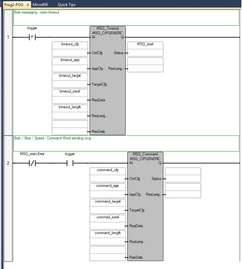
In order to control a drive over EtherNet, the Control Timeout class attribute must be set to a non-zero value.
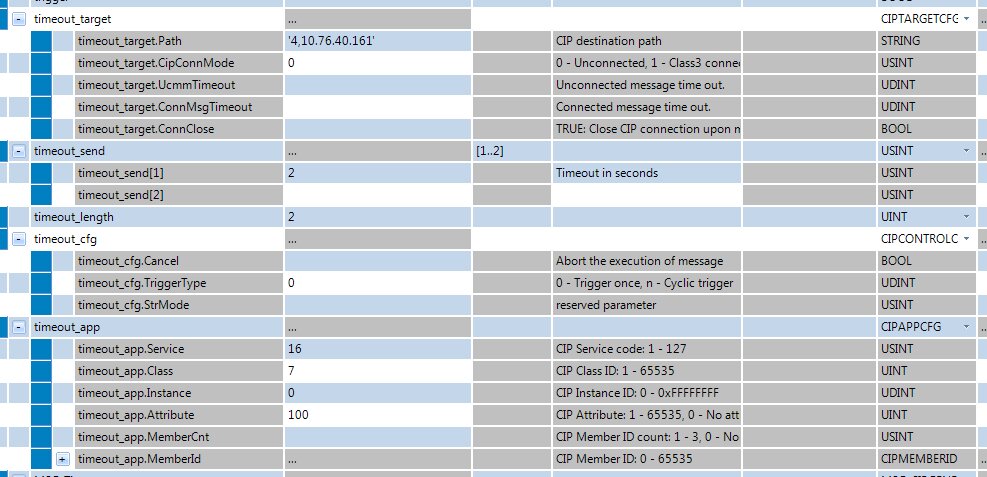
For more information on specific Services, Classes, Instances, and applications, refer to Appendix C, “Registry Objects,” in the PowerFlex 525 Embedded EtherNet/IP Adapter User Manual – Publication 520COM-UM001.
If Control Timeout is set, the main control message can be triggered with values like the example below.
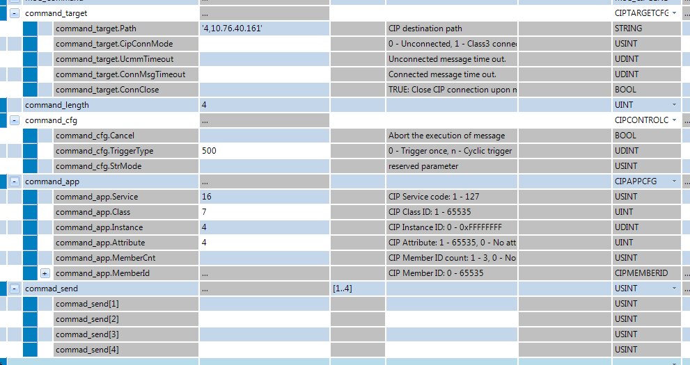
As a result of these MSG blocks, the controller sends an array of four USINTs. Elements 1 and 2 are the Logic Command Word, and elements 3 and 4 are the Speed Command, as shown below.
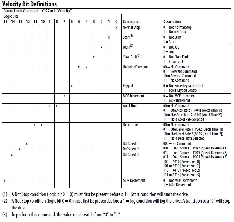
In addition, the following example shows how to trigger individual bits in a command word and set Speed Reference with the COP instruction.
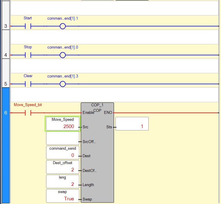
Note: Move_Speed with a value of 2500 is equal to 25 Hz on PowerFlex 525.
An example program can be found in the attachments of this technote.
Note: Although single messages as shown below can be sent to the drive, it is more practical to use the UDFB mentioned at the beginning of this technote.
Micro800 UDFB: EtherNet Communications with PowerFlex 750-Series, 520-Series and 4-Class Drives
This sample code contains multiple messages that allow full control of the drive and DataLinks, as well as status and feedback.
This UDFB reads the entire status word, but it only outputs several common bits that are available for all PowerFlex drives. The UDFB is not locked and can be modified to add bits from the Logic Status Word if required.
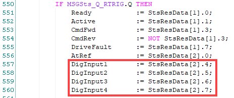
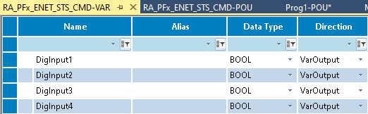
The standard UDFB does not include these bits because the definitions for bits 12-15 in the status word vary between PowerFlex drive families. If the intention is to read Logic Status Word bit 12 to bit 15, which are Digital Input Status bits for the PowerFlex 520-Series, the following can be added to the structured text. New local variables can also be created as shown below.