
 Tiếng Việt
Solutions, Industrial Automation, News
What Is Fiber Optic Cable and How Does It Work?
Fiber Optic Cable is the core foundation of the modern Internet and telecommunication infrastructure. Completely different from traditional copper cable, fiber optic uses light pulses to transmit data through pure silica glass fibers, providing superior speed, distance, and stability.
What is Fiber Optic Cable?
Definition of Fiber Optic Cable
Fiber optic cable is composed of extremely thin optical fibers (usually glass), strength members, and a protective outer jacket. The fiber optic acts as the transmission medium, where light pulses travel at extremely high speeds, carrying data from the transmitter to the receiver.
Unlike copper wire which transmits data using electrical signals, fiber optic uses light. The fiber manufacturing process requires extremely high purity glass to ensure light can travel long distances without signal loss. The fiber is produced through a preform creation process followed by fiber draw to achieve a standard diameter of 250 microns (thinner than a human hair).
The Role of Fiber Optic in Modern Transmission
In the digital age, fiber optic cable acts as the “backbone” of every transmission system. Its main roles include:
- Providing Massive Bandwidth: Transmitting significantly larger amounts of data compared to copper cable.
- Ultra-Long Distance Transmission: Supporting cross-city, cross-country, and transcontinental connections.
- Ensuring Safety and Security: It does not emit electromagnetic signals, making wiretapping extremely difficult.
Why Fiber Optic is Crucial in Network, Industrial, and Telecommunications Infrastructure
Fiber optic cable is a key factor for the development of:
- Telecommunications and the Internet: It facilitates the deployment of high-speed Internet (FTTH – Fiber to the Home) and is a mandatory component of international submarine cable systems.
- Industry: It ensures stability and Electromagnetic Interference (EMI) immunity in harsh factory environments and production lines with numerous electrical devices.
- Enterprise Networks and Data Centers: It delivers zero-latency, high-bandwidth speeds for data centers and large-scale local area networks.
Structure of Fiber Optic Cable
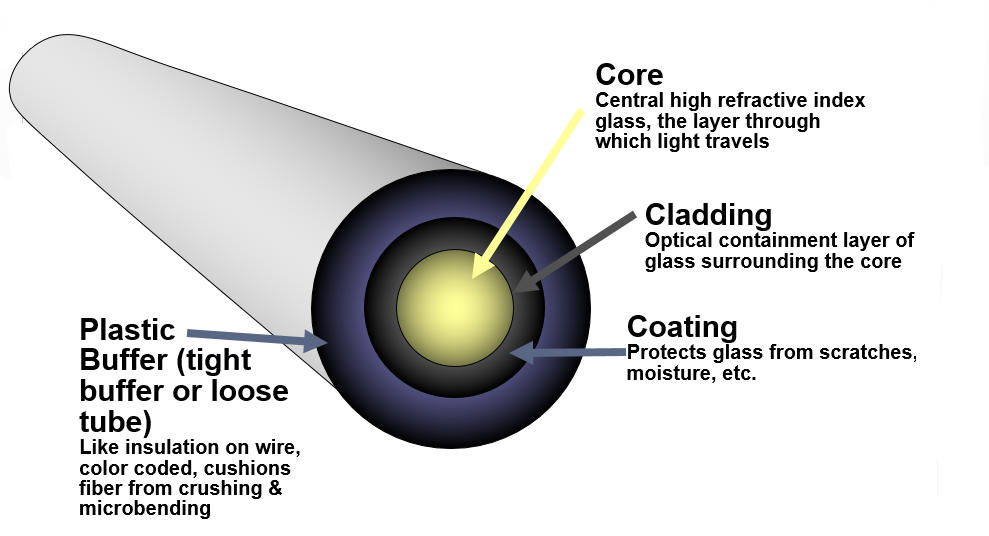
The basic structure of an optical fiber consists of three main components, often called the “three C’s”: Core, Cladding, and Coating.
Core
The Core is the central part of the optical fiber, made of transparent glass or plastic, where light actually travels. The size of the core determines the transmission mode (Singlemode or Multimode). Light is maintained within the core through the phenomenon of Total Internal Reflection.
Cladding
Wrapping around the core is the thin Cladding layer, also made of glass but with a lower refractive index than the core. The Cladding acts as a “perfect mirror,” continuously reflecting light back into the core, allowing the signal to travel the entire length of the fiber without escaping.
Coating – The Fiber Protection Layer
This is the polymer coating (usually two UV-cured layers) that encases the Cladding. The Coating protects the fragile glass fiber from scratches, moisture, and micro-bending forces that can cause signal attenuation.
Strength Members (Kevlar, FRP, Steel…)
To enable the fiber optic cable to withstand pulling, compression, impact, and bending during installation and use, reinforcing materials are added. Common materials include:
- Aramid Fibers (Kevlar): Lightweight, durable, and offer high tensile strength.
- Fiber Reinforced Plastic (FRP) Rods: Provide stiffness and compression resistance.
- Steel: Used in armored or rodent-resistant cables that require extremely high mechanical strength.
Outer Jacket
This is the outermost protective layer, made from polymer materials such as PE, PVC, or LSZH (Low Smoke Zero Halogen), depending on the installation environment. The Outer Jacket’s role is to resist environmental factors like moisture, UV rays, chemicals, and fire.
Distinguishing Loose Tube, Tight Buffer, Non-metallic, and Rodent-Resistant Cables
Cable structures are designed to suit specific applications:
- Loose Tube Cable: Fibers sit loosely within buffer tubes filled with moisture-blocking gel. This structure is common for outdoor and direct-burial applications.
- Tight Buffer Cable: The fiber is tightly coated right outside the Cladding layer. This structure is easier to terminate and is typically used for indoor applications or inside equipment racks.
- Non-metallic Cable: Contains no metal components, making it completely immune to electromagnetic fields and lightning strikes.
- Rodent-resistant Cable: Features an additional protective layer, often corrugated steel tape, to guard against damage from rodents and pests.
How Does Fiber Optic Cable Work?
The Principle of Total Internal Reflection
Fiber optic operation is based on the principle of Total Internal Reflection. When light travels from a high refractive index medium (Core) to a lower refractive index medium (Cladding), at an angle of incidence greater than the “critical angle,” the light is completely reflected back into the core. This process repeats continuously, keeping the light propagating along the entire length of the fiber.
How Light Travels in the Fiber Core
Light travels within the fiber core in the form of “modes” (transmission paths) or trajectories.
- Singlemode (SM): Only allows a single light mode to travel in a straight line, minimizing reflection and attenuation.
- Multimode (MM): Allows multiple light modes to travel simultaneously along different paths.
What is Signal Attenuation? Why Does it Occur?
Signal Attenuation is the reduction in the intensity of the light pulse as it travels along the optical fiber. Attenuation occurs due to several main reasons:
- Absorption: Light energy is absorbed by impurities in the glass (mainly hydroxyl groups).
- Scattering: Light is dispersed due to minor irregularities in the glass structure (Rayleigh Scattering).
- Modal Dispersion: Occurs only in Multimode cable, where light modes travel different paths and arrive at the destination at slightly different times, causing signal distortion.
- Bending: Excessive bending or sharp curves can cause light to escape the core (Micro-bending and Macro-bending).
Superior Advantages of Fiber Optic Transmission
Fiber optic transmission offers irreplaceable advantages:
- Supports Extremely High Bandwidth: The capability to transmit massive amounts of data, limited only by the terminal equipment.
- Virtually Unlimited Transmission Distance: Especially with Singlemode, signals can travel hundreds of kilometers with minimal need for amplification.
- Immunity to Electromagnetic Interference (EMI): Since it does not transmit electrical signals, fiber optic is completely unaffected by electromagnetic interference.
- High Security: Intruding a fiber optic cable requires physical access and usually disrupts the network, triggering immediate alarms.
Common Types of Fiber Optic Cables in Use
Classification by Transmission Mode
Singlemode (SM) Fiber Optic Cable
- Core Size: Very small (9 microns).
- Principle: Allows only one light mode to pass (single mode).
- Application: Very long-distance transmission (backbone networks, telecommunications, submarine cables).
- Common Types: G.652 (standard), G.655 (NZDSF), G.657 (bend-insensitive).
Multimode (MM) Fiber Optic Cable
- Core Size: Larger (50 or 62.5 microns).
- Principle: Allows multiple light modes to transmit simultaneously (multiple modes).
- Application: Short distances (LAN networks, Data Centers).
- Common Types (OM series):
- OM1 (62.5µm): Supports 1 Gbps up to 300m.
- OM2 (50µm): Supports 1 Gbps up to 600m.
- OM3 (50µm): Laser-optimized, supports 10 Gbps up to 300m.
- OM4 (50µm): Higher performance version of OM3, supports 10 Gbps up to 550m.
- OM5 (50µm): Optimized for SWDM (Short Wavelength Division Multiplexing) and wideband applications.
Classification by Structure
- ADSS (All-Dielectric Self-Supporting) Cable: Self-supporting, non-metallic cable, designed for overhead installation on utility poles.
- OPGW (Optical Ground Wire) Cable: Optical lightning protection cable, integrating fiber optics within the high-voltage power line’s ground wire, used for data transmission and line protection.
- Loose Tube Cable: Loose fiber structure in gel-filled tubes, good moisture resistance, used outdoors, for direct burial.
- Tight Buffer Cable: Fiber is tightly buffered, easy to terminate, used indoors, in racks, and Data Centers.
- Non-metallic Cable: Contains no metal, suitable for areas with lightning strike or electromagnetic interference risks.
Classification by Fiber Count
Fiber optic cables are manufactured with various fiber counts depending on project requirements. Common configurations include: 1FO, 2FO, 4FO, 8FO, 12FO, 24FO, 48FO, 96FO, and can extend up to hundreds of fibers for main backbone lines.
Applications of Fiber Optic Cable in Life and Industry
Fiber optic is a versatile technology, widely applied in many fields:
Telecommunications – Internet – Enterprise Networks
- Backbone Transmission: Connecting data centers, cities, and nations.
- FTTH (Fiber to the Home): Providing high-speed Internet directly to households.
- LAN/WAN Networks: Establishing internal network infrastructure for organizations, schools, and hospitals.
Automation – Factories – Production Lines
- Stable data transmission in harsh environments, high temperatures, and chemical exposure.
- Used in Industrial Ethernet networks for precise control.
Industrial Control (SCADA, PLC, DCS)
Fiber optic helps control and monitoring systems (SCADA, PLC, DCS) exchange high-speed, long-distance data without interference, ensuring reliability and safety for production processes.
Cameras – Security Surveillance – Long-distance Signal Transmission
Allows transmission of high-resolution video signals (HD/4K) over very long distances (many kilometers) that copper cable cannot meet, ideal for large-area surveillance.
Applications in Medicine (Fiber Optic Endoscopy)
Extremely thin optical fibers are used in endoscopic devices, simultaneously transmitting light into the body for illumination and transmitting images out for the doctor to observe.
Fiber Optic Installation, Deployment, and Splicing Process
The fiber optic installation process requires high technical skill and strict adherence to standards.
Cable Pulling – Suspension – Conduit Laying – Direct Burial
- Cable Suspension (Overhead): Using ADSS or steel-reinforced cables, installed on poles.
- Conduit Laying (Indoor/Ducts): Pulling cable through conduits and cable trays.
- Direct Burial: Placing the cable in protective ducts underground for increased durability and safety.
Cable Splicing with Fusion Splicer
To connect two segments of fiber optic cable or a cable to a pigtail, a Fusion Splicer is used. The splicer melts the two ends of the glass fiber and joins them together using high heat, creating a near-perfect splice with minimal attenuation (usually < 0.05 dB).
ODF Termination – Fiber Connectors – Adapters
- ODF (Optical Distribution Frame): A box or cabinet used to manage, protect, and distribute fiber optic connections.
- Fiber Connector: Connector types such as SC, LC, ST, FC attached to the fiber for connection to equipment.
- Adapter (Coupler): An intermediate device that connects two fiber optic connectors within the ODF.
Testing Equipment (OTDR, Power Meter…)
Testing equipment is mandatory to ensure the quality of the cable line:
- OTDR (Optical Time-Domain Reflectometer): Used to check total length, segment attenuation, and precisely locate breaks or faults on the cable line.
- Power Meter (Optical Power Meter): Used to measure the intensity of light transmitted through the cable and check total attenuation.
- Light Source: A device that emits light, used in conjunction with the Power Meter.
Attenuation Standards During Installation
The acceptable attenuation standard for each fusion splice is very low, typically ranging from 0.02 dB to 0.05 dB. The total line attenuation must comply with the cable manufacturer’s standards and project requirements.
Common Fiber Optic Cable Incidents
Cable Break – Fiber Damage – Abnormal Attenuation
- Cable Break/Fiber Damage: Common physical incidents due to installation errors, accidents, or natural disasters.
- Abnormal Attenuation: Occurs when splices are of poor quality, the cable is excessively bent, or water ingress occurs.
Submarine Cable Incidents (AAG / APG / IA)
International submarine fiber optic cable routes (such as AAG, APG, IA) are the backbone connecting the Internet to the world. Incidents on these routes (often due to ship anchors, earthquakes, or shark bites) seriously affect the speed of international Internet access in certain regions.
How to Inspect and Handle Incidents
- Inspection: Use OTDR equipment to accurately detect the location and type of attenuation (faulty splice, break point).
- Handling: Proceed to cut off the faulty cable/fiber segment, then perform fusion splicing to rejoin it. This process is repeated until the measured attenuation is within the permissible standard.
Benefits of Fiber Optic Cable
Fiber optic cable provides key advantages that make it the leading choice for high-performance network infrastructure. Here’s how fiber stands out:
1. Fiber Supports Very High Bandwidth Levels
Fiber optic cables, especially singlemode, offer the highest available bandwidth, carrying far more data than copper cables of the same diameter.
The cable itself isn’t the limitation—it’s the electronics connected to it. As technology advances, upgrading transceivers and other components allows you to maximize fiber’s potential without replacing the cable.
Additionally, fiber reduces latency, enabling faster downloads, quicker uploads, and smooth access to resources across both short and long distances.
2. Fiber is Inherently Secure
Fiber cables are highly secure because they don’t radiate signals that can be intercepted.
Tapping into a fiber cable requires physically accessing and cutting into it, which typically brings down the network and triggers immediate alerts—making unauthorized access extremely difficult.
3. Fiber is Intrinsically Safe
Since fiber transmits data via light rather than electricity, it is safe to handle, eliminating the risks associated with electrical cables like sparks, shocks, or fires.
4. Fiber Withstands Water and Temperature Fluctuations
Fiber optic cables are resistant to environmental challenges such as moisture, rain, and extreme temperatures.
Even in severe weather or when exposed to lightning, fiber performance remains unaffected because it contains no metallic elements to conduct electricity. This makes it ideal for outdoor, industrial, and long-distance applications.
5. Fiber is Immune to EMI
Unlike copper cables, fiber does not carry electric current and is completely immune to electromagnetic interference (EMI) and crosstalk.
This ensures stable, uninterrupted data transmission, even in environments with dense electronic equipment.
Developing optical fiber components for more than 50 years, Belden is a leading supplier of high-quality, cost-effective fiber cabling systems. Our FiberExpress Ultra High Density (FX UHD), FX ECX (FiberExpress Enterprise Closet X) and DCX Systems are the culmination of decades of experience and expertise across a variety of applications, including data centers, premise and campus network backbone infrastructures, fiber-to-the-desk (FTTD) and horizontal and centralized cabling systems.


Comparison Between Fiber Optic and Traditional Copper Cable
| Feature | Fiber Optic (FO) | Copper Cable |
|---|---|---|
| Transmission Speed | Very high (Gbps – Tbps), unlimited. | Limited (max 10 Gbps over 100m for Cat.6A). |
| Signal Transmission Distance | Very long (tens, hundreds of km for SM). | Short (usually a maximum of 100m). |
| Noise and Attenuation | Completely immune to EMI, extremely low attenuation. | Susceptible to EMI and crosstalk, high attenuation over distance. |
| Bandwidth | Virtually unlimited, easily upgradable with equipment. | Limited by wire diameter and frequency. |
| Investment Cost & Operating Efficiency | High terminal equipment cost, low operating cost, long-term efficiency. | Low initial cost for short distances, operating costs increase if multiple amplifiers are needed. |
Transmission Speed
Fiber optic transmits data using light, allowing speeds up to Terabits per second (Tbps), whereas copper cable transmits using electrical signals, limiting speed and making it prone to quality degradation.
Signal Transmission Distance
Due to extremely low attenuation, singlemode fiber optic cable can transmit signals over tens, even hundreds of kilometers while maintaining signal clarity, far exceeding the 100-meter limit of most copper cables.
Noise and Attenuation
This is the most outstanding advantage. Fiber optic is made of dielectric material (glass/plastic) and is completely unaffected by Electromagnetic Interference (EMI) or Radio Frequency Interference (RFI), ensuring stable signal quality. Copper cable always requires shielding measures to combat noise.
Investment Cost & Operating Efficiency
While fiber optic transceivers and initial installation may be more expensive, in the long run, the performance, durability, and ability to upgrade bandwidth without replacing the cable make the Total Cost of Ownership (TCO) of fiber optic more efficient for long-distance and high-bandwidth applications.
Frequently Asked Questions about Fiber Optic Cable (FAQ)
Does Fiber Optic Cable carry electricity? No. Fiber optic cable only transmits light signals and carries absolutely no electricity. This makes it safe to handle and immune to electrical risks such as sparks or fire.
What are the key advantages of Fiber Optic Cable? Key advantages include: extremely high bandwidth, long-distance transmission, immunity to electromagnetic interference, and high data security.
How far can Fiber Optic Cable operate? The operating distance depends on the cable type:
- Singlemode: Can operate continuously for hundreds of kilometers.
- Multimode: Best within a few hundred meters (e.g., OM4 supports 10 Gbps over 550m).
Why is Fiber Optic Cable often laid under the sea? Fiber optic cables are laid under the sea to connect the Internet between continents. The reason is that they provide the massive bandwidth necessary for global Internet traffic and can transmit signals over enormous distances without requiring frequent amplification.
Can a broken Fiber Optic Cable be spliced back together? Yes. A broken fiber optic cable can be fully reconnected using specialized thermal splicing techniques with a Fusion Splicer.
Servo Dynamics Engineering: Authorized Distributor of Belden in Vietnam
For over 50 years of developing fiber optic components, Belden has become a leading supplier of high-quality, cost-effective fiber optic systems. Belden’s FiberExpress Ultra High Density (FX UHD), FX ECX (FiberExpress Enterprise Closet X), and DCX Systems are the result of decades of experience and expertise, serving diverse applications such as data centers, internal network infrastructure, campus backbones, Fiber To The Desk (FTTD) systems, and horizontal or centralized cabling systems.
Servo Dynamics is proud to be the authorized distributor of Belden in Vietnam, providing world-class cable and connectivity solutions to the domestic market. As a trusted partner, we offer the full line of Belden’s high-performance products, including Belden fiber optic cable, industrial Ethernet solutions, and network accessories. With a strong commitment to quality, innovation, and customer service, our team ensures that businesses in Vietnam have access to advanced, reliable technology to operate efficiently and stay connected in today’s rapidly digitizing world.
Learn more

Industrial Communication Cables: What Are They? Classification, Structure & Detailed Applications
Industrial Communication Cable is the indispensable backbone component in every modern automation system and process [...]
Mar

Servo Dynamics become an Authorized Distributor of Belden in Vietnam
Belden: Empowering Industries with Quality and Innovation Belden was founded in 1902, making it one [...]
Feb

What is Industrial Electrical Cable? A Guide to Choosing the Right Cable
Industrial electrical cables play a crucial role in energy transmission and ensuring the stable operation [...]
Jan

What is a Network Switch? Classification, Functions, and How It Works
In the era of digitalization, especially within industrial manufacturing and automation environments, the Network Switch [...]
Mar

