
 Tiếng Việt
Consulting, Stratus Technologies
Fault Tolerance: Characteristics, Benefits, and Applications

In the world of manufacturing, industry, and digital infrastructure, no system can completely avoid failures. However, the difference between a business that comes to a complete halt and one that maintains production lies in a key factor: Fault Tolerance.
Fault tolerance is not just a feature but a core design philosophy that ensures your system continues to operate smoothly with zero downtime, even when critical components fail. Let’s take a deeper look at the concept, operating mechanisms, and practical applications of fault tolerance in electrical systems and industrial control panels.

What Is Fault Tolerance?
Why Is Fault Tolerance Needed in Electrical Systems and Industrial Panels?
Fault tolerance is extremely important because electrical systems and industrial control panels are often the lifeblood of production processes.
- Ensure continuous operation (Zero Downtime): In industries such as semiconductors, pharmaceuticals, automotive manufacturing, or data centers, even a few minutes of downtime can cause massive financial losses or data loss.
- Operational and asset safety: Fault tolerance helps quickly detect and isolate dangerous faults (such as short circuits or prolonged overload), protecting expensive equipment and reducing the risk of fire and explosion.
- Maintain product quality: Sudden failures in control systems can ruin an entire batch of products in production.
Distinguishing “Fault Tolerance” from “Load Capacity” and “Mechanical Strength”
| Attribute | Fault Tolerance | Load Capacity | Mechanical Strength |
|---|---|---|---|
| Definition | The ability to maintain operation when a component fails (fault). | The ability to operate under a specified maximum load/capacity. | The ability to resist deformation or destruction under physical forces. |
| Scope | Electrical systems, control systems, IT. | Electrical equipment (current, power), structures. | Material structures (steel, concrete, electrical enclosure housing). |
| Mechanism | Redundancy, Failover switching. | Designing dimensions and materials according to rated specifications. | Selecting materials with high tensile, compressive, and bending strength. |
| Example | ATS panel automatically switching to generator power. | Maximum allowable current of an MCCB. | Impact resistance of an electrical enclosure. |
Fault tolerance focuses on the functionality of the system, while load capacity and mechanical strength focus on the durability of physical components.
Fault Tolerance Architecture

Fault-tolerant architectures typically rely on several strategies:
- Hardware Redundancy: Duplicating critical hardware components such as CPUs, memory, storage, and network interfaces.
- Software Redundancy: Using software methods such as checkpointing, process replication, and distributed consensus to maintain continuous operation.
- N+1 Redundancy: Including one additional backup component beyond what is required for normal operation, allowing the system to keep running even if one component fails.
- Active-Active: All redundant components operate simultaneously, ensuring both backup capability and improved performance.
- Active-Passive: One component operates as the primary, while the backup remains idle and only takes over when the primary fails.
How a Fault-Tolerant System Works
The operating mechanism of a fault-tolerant system is based on a continuous loop: Error Detection -> Isolation -> Failover Switching -> Recovery.
Redundancy Mechanism
Redundancy is the foundation of all fault-tolerant architectures. It involves duplicating critical components to ensure that there is always at least one replacement component ready to operate.
Hardware redundancy (transformers, MCCB, ACB, electrical devices)
- Transformers: Installing two or more transformers (e.g., N+1 or 2N) so that one transformer can take over the load when another fails or needs maintenance.
- Switching devices (ACB, MCCB): Using redundant switching devices in ring main units (RMU) or main switchboards (MSB), allowing flexible source transfer.
- Power supply: Using redundant UPS (N+1) and dual power supplies for control devices.
Redundancy in communication links or control circuits
- Communication networks: Using ring topologies such as EtherNet/IP Ring or PROFINET Ring, where data can flow in both directions, ensuring the link remains operational even if one cable is broken.
- Control circuits: Using redundant PLCs in Hot Standby mode (primary and secondary PLCs running in parallel with continuous data synchronization), allowing immediate switchover (zero changeover time) when the primary PLC fails.
Safe Switching (Failover & Backup Switching)
Failover is the process of automatically transferring functionality from a failed primary component to a backup component.
- This process must occur almost instantaneously (often under 100 ms in critical control systems) so that users or production processes do not notice any interruption.
- A typical example is an Automatic Transfer Switch (ATS) in an electrical panel, which automatically switches the power source from the grid to the generator when the grid fails.
Fault Detection Capability
A fault-tolerant system must be able to detect when a component fails.
- Continuous monitoring: Using sensors, multifunction meters, protective relays, and built-in diagnostics (such as PLC diagnostics, temperature monitoring, vibration monitoring).
- Voting Algorithms: In 2N or 3N (triple-redundant) systems, outputs are compared. If one result differs (for example, 2 out of 3 match), the component producing the deviating result is considered faulty and isolated.
Isolation and Self-Recovery Capability
After detecting a fault, the system must:
- Isolation: Quickly disconnect the faulty component to prevent fault propagation. For example, protective relays trip MCCBs/ACBs to clear short circuits.
- Self-Healing: Restart or restore the most recent state for the backup component, or even attempt to restart the faulty component if the error is temporary.
Levels of Fault Tolerance in Industry
Fault tolerance is classified according to the complexity level and ability to withstand failures.
No Fault Tolerance
- Only a single component exists for each function.
- Single Point of Failure (SPOF): Any failure leads to a complete shutdown.
- Example: A server without a UPS; a single PLC without redundant power.
Low Fault Tolerance – Basic Level
- Using redundancy at the utility or power level (e.g., N).
- Example: Using a UPS or dual power sources. If the primary source fails, the backup takes over, but if both fail, the system stops.
High Fault Tolerance
- Using N+1 or 2N redundant architectures (Active-Active or Hot Standby).
- The system can withstand one or more component failures without any service interruption.
- Example: Hot Standby redundant PLCs (2N) or a switchboard system with two transformers (N+1).
High Availability vs. Fault Tolerance
| Criteria | High Availability (HA) | Fault Tolerance (FT) |
|---|---|---|
| Goal | Minimize downtime (short, acceptable outages). | Completely eliminate downtime (Zero Downtime). |
| Recovery time | From a few seconds to a few minutes (fast recovery after faults). | Almost instantaneous (0 milliseconds – 0 seconds). |
| Mechanism | Failover, clustering, load balancing. | Comprehensive redundancy, synchronous processing. |
| Cost & complexity | Lower. | Higher (requires specialized hardware and software). |
HA is a subset of FT. HA focuses on fast recovery after a fault, while FT focuses on maintaining continuous operation without interruption during the failure itself.
Benefits of Fault Tolerance in Electrical Panels and Power Systems
Ensuring continuous operation (Zero Downtime)
The core benefit is maintaining 24/7 production. This eliminates losses due to shutdowns, process restarts, and other costs related to unplanned downtime.
Protecting equipment and reducing fire risk
Fast fault detection and isolation mechanisms (such as protective relays in panels) prevent prolonged short circuits, overheating, or overloads that cause permanent damage to equipment and increase fire risk.
Extending the lifespan of electrical equipment
By preventing sudden failures and providing stable operating conditions, fault-tolerant systems reduce thermal and electrical stress on components, thereby extending the life of transformers, MCCBs, ACBs, and motors.
Reducing maintenance costs and troubleshooting time
Redundant systems allow scheduled maintenance on one component while the backup continues operating. This helps avoid emergency maintenance costs and reduces unplanned troubleshooting time.
Ensuring operational and production safety
In heavy industries, sudden power loss or loss of control can pose serious risks to operators and equipment. Fault tolerance helps keep safety functions operating continuously.
Benefits of Fault Tolerance
- Increased availability: This is the primary benefit. Fault tolerance minimizes downtime, ensuring that systems remain operational even when components fail. This is essential for applications that require continuous uptime, such as e-commerce platforms, financial systems, and emergency services.
- Improved reliability: By handling failures smoothly, fault tolerance makes systems more reliable and predictable. Users experience fewer disruptions and can trust that the system will be available when needed.
- Enhanced data integrity: Fault-tolerant mechanisms such as data replication and error-correcting codes help protect data from loss or corruption in the event of storage or transmission failures.
- Reduced maintenance costs: While there are upfront costs associated with implementing fault tolerance, it can lead to long-term savings by reducing the need for emergency repairs and replacements due to unexpected failures.
- Improved safety: In safety-critical systems such as aircraft control or medical equipment, fault tolerance is essential to ensure safety and prevent potentially life-threatening consequences of failures.
- Continuous operation: Fault tolerance helps organizations maintain business operations during disruptions, minimizing financial losses and reputational damage.
Limitations of Fault Tolerance
- Increased complexity: Designing and implementing fault tolerance adds complexity to system architecture. It requires careful planning, coordination, and testing.
- Higher costs: Deploying redundancy, specialized hardware, and complex software increases the initial cost of building the system.
- Performance overhead: Some fault-tolerance mechanisms, such as data replication and voting algorithms, can introduce performance overhead, potentially slowing the system during normal operation.
- Difficult testing: Thoroughly testing fault-tolerance mechanisms can be challenging because it requires simulating a wide range of fault scenarios.
- Risk of fault propagation: If not carefully designed, a fault in one component can trigger cascading failures in other components, despite fault-tolerance measures.
High Availability vs. Fault Tolerance
High Availability (HA) and Fault Tolerance (FT) are both important strategies for ensuring system reliability and minimizing downtime, but they address this goal in different ways. High availability focuses on reducing downtime by implementing redundancy and failover mechanisms, ensuring that systems can recover quickly after a failure, though brief interruptions may still occur.
It is ideal for environments where minimizing service disruptions is important but short periods of downtime are acceptable.
Fault tolerance goes a step further by ensuring there is no downtime even when components fail. It achieves this through full redundancy, where backup systems automatically take over without impacting performance. Although fault tolerance is more complex and expensive, it is essential for mission-critical systems that require continuous operation without any service interruptions, such as in healthcare, aerospace, or finance.
Industrial Applications of Fault Tolerance
Industrial electrical panels and control systems
Distribution boards (MSB, DB), ATS panels, capacitor banks
- ATS panels: The most basic failover application, automatically switching power from the grid to the generator and back, ensuring uninterrupted power supply.
- MSB/DB panels: Using bus-tie architectures with redundant ACBs, allowing any bus section to be isolated for maintenance or in case of faults.
Motor Control Centers (MCC), PLC & SCADA
- Redundant PLCs: Using dual PLCs (Siemens S7-400H, Rockwell ControlLogix Redundant, Stratus ztC Edge/everRun) in Hot Standby mode to avoid loss of process control.
- SCADA: Installing redundant SCADA servers (Primary/Secondary) to ensure continuous data acquisition and visualization.
Transformers and switching devices
Overload tolerance of transformers
Modern transformers have controlled short-term overload capability. This is a form of thermal fault tolerance, allowing transformers to operate above their nominal rating for a short period, which is useful when one transformer fails and the remaining unit must temporarily carry additional load.
Short-circuit withstand capability of ACBs and MCCBs
Switching devices such as ACBs and MCCBs are designed to withstand extremely high short-circuit currents during the breaking time (from 10 ms to 100 ms) without being destroyed. This ensures they can successfully isolate faults.
Automated production systems and robots
Robots and automated production lines use redundant sensors and controllers (redundant sensors, dual-channel safety relays) so that a single sensor failure does not stop the entire process.
IT infrastructure – Data Centers – Cloud/Edge
Servers, data centers, and edge computing systems are some of the most advanced environments for fault-tolerant technologies, using solutions such as fault-tolerant virtualization and parallel processing systems.
Practical Examples of Fault Tolerance
Switchboards with automatic ATS transfer
An ATS panel (Automatic Transfer Switch) is a classic example of failover in industrial power systems. When the grid (main source) goes down, the ATS automatically sends a start signal to the generator and switches over to the backup source.
Redundant VFDs/PLCs
In systems that require extremely precise speed/torque control (such as paper or steel production), PLCs or VFDs are configured in hot standby redundancy. If the primary device fails, the backup takes over without changing speed or operating conditions.
Transformers operating in controlled overload
In an N+1 scenario, if one transformer fails, the remaining transformer is closely monitored for temperature and load to safely operate in temporary overload conditions until the faulty transformer is repaired.
Bearings, bolts, steel… in load-bearing structures
Although this falls under mechanical strength, designing structures with high safety factors (over-designing) is also a form of mechanical redundancy. It ensures that even with minor defects or short-term overload, the structure does not collapse, indirectly maintaining industrial system operation.
How to Design a Highly Fault-Tolerant System
Load–current–power analysis
The first step is to accurately determine power, current (operating current, short-circuit current), and dynamic load requirements. This analysis helps identify Single Points of Failure (SPOF) in the system and guides appropriate redundancy decisions (e.g., whether N+1 or 2N is needed).
Selecting the right devices: MCCB/ACB, transformers, UPS, PLC
- Switching devices: Select MCCBs/ACBs with high breaking capacity (Icu, Ics) and good selectivity so that only the faulty circuit is isolated without affecting the rest of the system.
- Transformers: Choose units with high thermal class and reserve capacity.
- PLC/control devices: Prioritize product lines designed for redundancy applications (Redundancy Ready).
Building N+1, N+2 redundancy systems
- N+1: Provide N required components plus one backup component. (E.g., 2 pumps, only 1 needed to operate. If 1 fails, the other still meets the load.)
- N+2: Provide N required components plus two backup components. This offers extremely high fault tolerance, allowing the system to withstand two simultaneous failures.
Fault Testing and Periodic Assessment
No fault-tolerant system is complete without testing.
- Fault Injection Testing: Simulate failures by disconnecting power, unplugging cables, or intentionally faulting a component to verify that the failover mechanism works automatically and seamlessly.
- Periodic assessment: Regularly inspect and maintain backup components, as redundant elements may have already failed without being detected.
How everRun® Enterprise and ztC™ Edge Provide Fault Tolerance

The Stratus everRun Enterprise software and Stratus ztC Edge edge computing platforms both use software-based approaches to deliver fault-tolerant applications and protect data.
The main challenge with software-based approaches is replicating data efficiently while minimizing system load. Insufficient replication can lead to long recovery times. Over-replication, on the other hand, consumes excessive system resources just to ensure availability.
everRun Enterprise and Stratus Redundant Linux – the operating platform for the ztC Edge solution – replicate all data written to disk (for high-availability workloads) and use a unique checkpointing engine to continuously replicate in-memory data and CPU state (for fault-tolerant workloads).
All I/O operations are queued until checkpointing completes and is verified. Proprietary algorithms automatically adjust checkpoint frequency based on the type and amount of data change as well as I/O traffic.
When a node fails, the system pauses for two seconds to avoid a split-brain condition, helping achieve recovery times under five seconds – below the TCP/IP thresholds for queuing and retransmission.
Beyond the highly efficient checkpointing engine, Stratus solutions stand out for their operational simplicity. No application or guest operating system modifications are required to make them cluster-aware. No additional failover scripting is needed to ensure application availability and data integrity. You simply install the application in a virtual machine and start it to make it fault-tolerant.
How ftServer® Provides Fault Tolerance
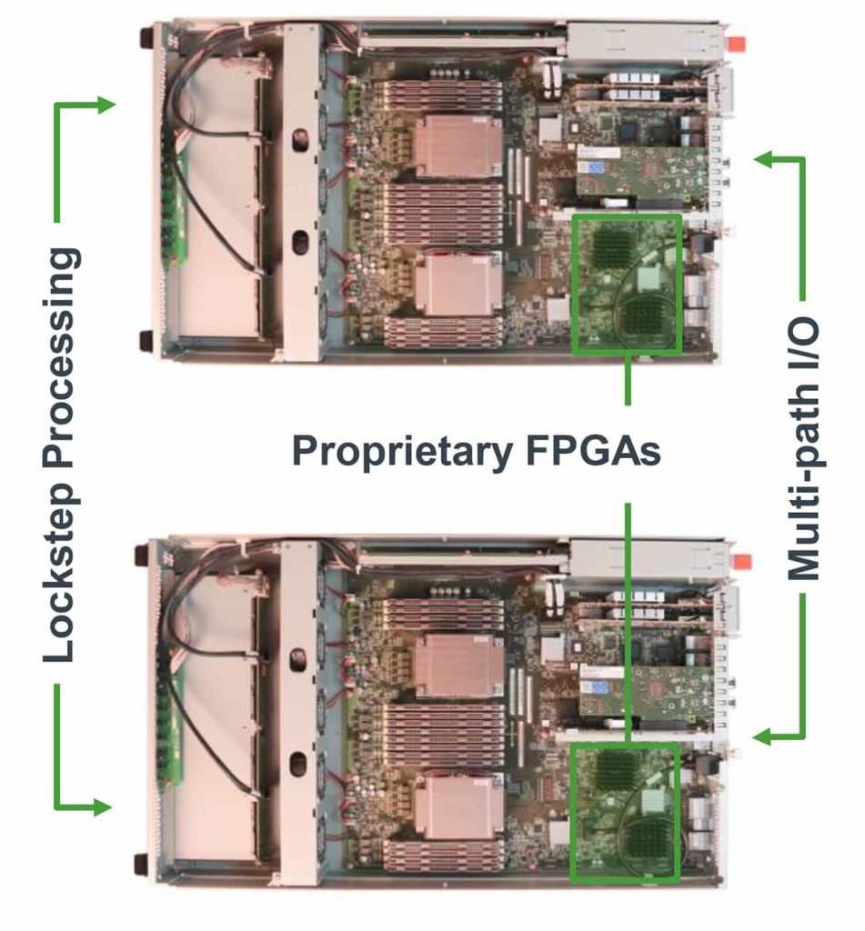
Stratus ftServer uses a hardware-based approach to provide fault-tolerant applications and data.
The main challenge with hardware-based approaches is ensuring precise synchronization of processes and data flows – making sure that every operation occurs at exactly the same time on both nodes of the redundant system.
Stratus ftServer uses proprietary field-programmable gate arrays (FPGAs) to ensure absolutely synchronous processing on the two identical halves of the ftServer system. Two customer-replaceable units (CRUs) operate in parallel. Each unit can take on the role of primary or secondary server as needed, executing the same processes simultaneously.
With ftServer, there is no recovery time when a component or a CRU fails. The remaining CRU immediately assumes the role of primary server until the unavailable CRU is replaced. For organizations that cannot tolerate even a single second of unplanned downtime, Stratus ftServer is a compelling option.
In addition to using FPGAs and synchronous processing, Stratus ftServer is also distinguished by its operational simplicity. Applications, virtualization platforms, or guest operating systems installed on ftServer do not require special modifications or configurations to become fault-tolerant.
Servo Dynamics Engineering: Master Distributor of Penguin Solutions (formerly Stratus) in Vietnam
Servo Dynamics is proud to be an authorized distributor of Penguin Solutions, a global leader in fault-tolerant technologies. We deliver advanced solutions such as ftServer®, everRun®, and ztC™ Edge, designed to ensure continuous operation, maximum data protection, and enhanced productivity across all industrial and enterprise environments.
Why Choose Servo Dynamics?
- Official Stratus partner: Commitment to providing genuine products and high-quality services.
- End-to-end solutions: From software to hardware, technologies like ftServer®, everRun®, and ztC™ Edge meet every requirement for reliability and performance.
- In-depth support: An experienced engineering team always ready to advise and support customers with dedication.

