
 Tiếng Việt
Consulting
Bearingless Encoder: Definition, Classification, Structure, Operational Principle, and Industrial Applications
What is a Bearingless Encoder: Definition, Classification, Structure, Operational Principle, and Industrial Applications
Definition – Classification – Structure – Operation
What is a Bearingless Encoder?
A bearingless encoder is a type of encoder that uses magnetic sensors to measure the speed, position, and direction of rotation of a machine shaft. The most notable feature of this product line is that it has no rotating shaft or internal bearings.
Unlike traditional encoders, bearingless encoders are mounted directly onto the existing machine shaft via a magnetic rotor. Because bearingless encoders do not need to support the shaft themselves, their usable space diameter is directly proportional to the actual shaft diameter of the device. Therefore, with high-capacity products like Baumer’s HeavyDuty, the operating shaft of a these encoder can reach over 3 meters.
With its “bearingless” design, the encoder has virtually no wear parts, resulting in high durability and stable operation in harsh environments and at high speeds.
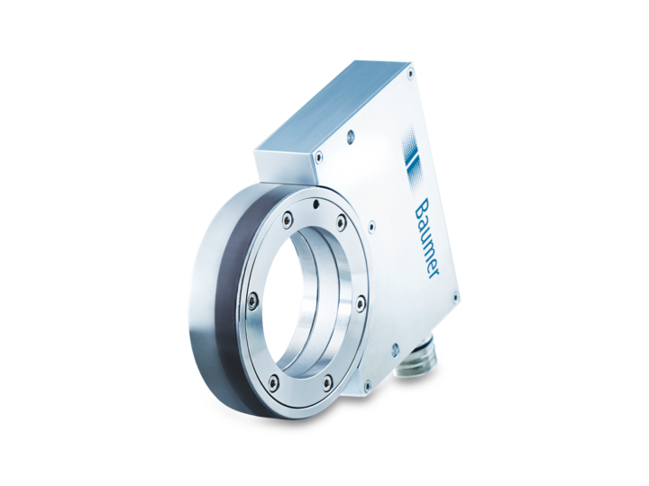
A Baumer’s Bearingless Encoder
Classification:
Similar to traditional encoders, bearingless encoders can be classified in four main ways:
Based on output signal type (Incremental / Absolute)
- Incremental signal: Generates square-wave pulses (A, B, Z phases) based on changes in position; requires homing at startup and loses position data when power is lost.
- Absolute signal: Provides a unique binary code for each position and retains position information even during a power loss.
Based on sensing principle (Magnetic / Inductive / Hybrid stepper–servo)
- Magnetic: Uses a magnet and Hall sensors to read position.
- Inductive: Uses electromagnetic fields to detect changes in metal.
- Hybrid (stepper + servo principle): Uses a mechanism similar to a miniature motor to determine position.
Based on mechanical configuration (Ring / Segment / Large‑bore / Tape)
- Ring: Circular encoder mounted around large shafts.
- Segment: A partial ring, assembled from multiple curved segments.
- Large‑bore: Hollow‑shaft encoder with a very large inner diameter for oversized shafts.
- Tape: Uses a long magnetic tape wrapped around the shaft to measure position along its circumference.
Based on application class (High‑speed / Heavy‑duty / Safety / General)
- High‑speed: Designed to maintain accurate readings at very high rotational speeds.
- Heavy‑duty: Withstands vibration, shock, dust, oil, and high temperatures.
- Safety: Complies with safety standards (SIL/PL) for machines that require protection of human operators.
- General: Standard encoders for typical applications without special requirements.
 Types of Baumer’s Bearingless Encoder
Bearingless magnetic encoder structure:
Magnetic Rotor
The magnetic ring is a multi-pole magnetic ring pressed/clamped directly onto the machine shaft, rotating synchronously with the shaft to create a cyclically varying magnetic field for the reader.
Because bearingless encoders do not have a shaft and bearings inside, the rotational movement of the encoder is supported by the machine’s bearings, and the magnetic ring is the only moving part in the measurement system. This eliminates mechanical wear and tear and enhances durability in harsh environments (dust, moisture, vibration/shock) thanks to non-contact measurement.
Sensor Head
The sensor head of a bearingless encoder is usually a multi-point sensor, allowing simultaneous integration of a multi-point magnetic or inductive sensor network. This is the stationary part, positioned opposite the magnetic ring across an air gap, integrating the magnetic sensing element (Hall/AMR/GMR/TMR or inductive sensor) and pre-processing circuit.
Air Gap
The air gap is the space between the magnetic ring and the sensor head. This is the most important installation parameter, because the signal amplitude is proportional to the magnetic flux density at the reader. With a larger air gap, the magnetic flux weakens, thus requiring a more sensitive reader and/or stronger magnetism.
Compared to other types of encoders with magnetic clearance, such as magnetic and inductive encoders, bearingless encoders have the largest magnetic clearance, with Baumer’s bearingless encoder products having axial tolerances of ±3 mm and radial tolerances of 2–3 mm.
Processing & Communication Circuit
The processing & communication circuit is integrated directly into the sensor head, handling noise filtering, linearization, interpolation, and protocol encoding processes. It converts the analog signal from the sensor into encoded pulses in A/B/Z, Sin/Cos, SSI/BiSS-C, CANopen, or IO-Link depending on the product line. The communication circuit then outputs information on position, speed, direction of rotation, and provides real-time diagnostics.
Because bearingless encoders lack bearings and optical discs, the processing circuit must stabilize the signal, automatically compensate for errors, and monitor operating conditions to ensure long-term accuracy.
Operating Procedure
Generating a variable magnetic field from the magnetic ring
When the device is powered on, the electronic circuit in the sensor head performs a startup process and prepares to read the magnetic field signal. When the machine shaft starts, the N/S poles on the magnetic ring sweep across the sensor head, creating a periodically varying magnetic field in the form of a sinusoidal/cosine analog voltage or a raw induced signal. This information reflects the instantaneous angle and rotational speed of the shaft.
Analog Preprocessing (AFE) → Signal-to-Noise Ratio (SNR) Stabilization
The raw magnetic signal passes through amplification, filtering, and channel equalization to improve the signal-to-noise ratio before being fed into the digital block (DSP/FPGA). AFE helps stabilize amplitude/phase as the machine accelerates, reducing the risk of amplitude variation due to magnetic gap and runout.
Real-time data processing
From the very first rotations, the digital processing unit performs:
- Interpolation of sine/cosine pairs to achieve high resolution (PPR/bit) for speed/position control.
- Linearization to reduce non-linear errors due to magnetization, installation, and heat.
- Auto-calibration to maintain signal smoothness equivalent to optical but with magnetic durability.
Real-time magnetic gap monitoring → early shaft misalignment error warning
In new generation bearingless encoders, the processing circuit activates Air-Gap Monitoring from the moment of startup: measuring the actual gap between the rotor and the reader, thereby detecting very small changes due to shaft misalignment, bearing wear, etc., and sending warning flags to the control system for predictive maintenance.
Encode and output signals via standard communication
Once stable, the encoder outputs data via A/B/Z (TTL/HTL/RS-422), Sin/Cos 1Vpp, or absolute (SSI/BiSS-C/CANopen).
Some models integrate IO-Link for both input and output position/speed measurement, and remote measurement of signal quality indicators, magnetic gap, temperature, warnings, etc.
Technical Standards – Usage Standards
| Standard Group | Specific Parameters | Brief Explanation |
| Resolution | 1.024 – 65.536 ppr (incremental)
Up to 18–22 bit (absolute) |
High resolution range thanks to digital interpolation; sufficient for servos, large motors, turbines and high-speed conveyors. |
| Interface | HTL 10–30 VDC,
TTL/RS‑422 5 VDC, Sin/Cos 1 Vpp, SSI, BiSS‑C, CANopen, IO‑Link, PROFINET |
Compatible with European and Japanese PLC/Drive standards: Siemens, Beckhoff, Rockwell, Mitsubishi. |
| Power Supply | 4,75–30 VDC | Wide power supply range for easy compatibility with control cabinets. |
| Operating Temperature | –40°C…+100°C
(Some models can go up to +105°C) |
Suitable for outdoor environments or areas near motors/extruders. |
| IP Protection Rating | IP67 / IP68 / IP69K | IP69K provides high-pressure water resistance, suitable for CIP/SIP washing, environmental vehicles, and wind turbines. |
| Max Speed | 10.000 – 12.000 rpm (incremental)
6.000 – 8.000 rpm (absolute) |
Suitable for use with servos, AC motors, and high-speed conveyors. |
| Tolerance – Air Gap | Axial: ±2,0 – ±3,0 mm
Radial: ±2,0 – ±3,5 mm |
10–15 times larger than optical encoders, allowing for greater tolerance to the machine’s natural eccentricity. |
| Support Shaft Sizes | Ø30 mm → Ø3.000 mm+
(HeavyDuty Baumer) |
Suitable for large motors, wind turbines, rolling mills, and grinding mills. |
| Vibration Resistance | ≤ 20 g (10…2.000 Hz) | No pulse loss during continuous vibration. |
| Shock Resistance | ≤ 200 g / 6 ms | Better shock resistance than optical encoders (typically only ~30–50 g). |
| EMC Noise Resistance | EN 61000‑6‑2 / EN 61000‑6‑4 (class Industry) | Unaffected by large motors, VFDs, welding, and high-power busbars. |
| Corrosion Rating | C3 – C5‑M (Marine standard) | Suitable for chemical environments, seawater, salt spray, and environmental vehicles. |
| Magnetic Gap | 0.5 – 2.5 mm depending on model (with Air-Gap Monitoring warning) | Ensures signal stability even with mechanical vibrations. |
| Accuracy | ±0,3°… ±0,05° (depending on Absolute series) | Sufficient for high-precision position and speed control. |
Advantages of Bearingless Encoders Over Traditional Encoders:
Reduced Mechanical Wear
Because bearingless encoders have no bearings or rotating shafts inside, there is no mechanical contact between the components. Therefore, there is no wear on the components and no need for periodic maintenance.
This characteristic allows bearingless encoders to operate stably for extended periods, even in heavy industrial production environments or environments requiring continuous machine operation.
Less Affected by Environmental Factors (Dust, Oil, Moisture)
Bearingless encoders use magnetism or induction to measure rotational speed instead of optics, thus eliminating the risk of dust, oil vapor, or moisture obscuring the optical disc and distorting the results. This allows bearingless encoders to operate faster, as the electronic circuits do not require inspection and cleaning of the machine.
Current-Resistant Shaft Current
In bearingless encoders, the electrical sensor heads are separated from the machine shaft. This prevents currents from the main machine from entering the bearingless encoder’s electronic circuitry, completely eliminating the risk of internal component damage due to leakage current.
Resistant to Mechanical Vibration/Shock
Because there are no bearings and/or optical discs, bearingless encoders are not prone to component breakage or damage from mechanical impact, and there are no thin discs to shift or crack due to overuse.
Stable Operation with Slight Eccentricity
A strong advantage of bearingless encoders is their ability to maintain a stable measurement signal even with slight shaft eccentricity (radial/axial shift). Thanks to their non-contact design and wide installation tolerances, encoders are not significantly affected by mechanical oscillations, vibrations, or shaft runout, which are common in heavy industrial production lines.
Less prone to thermal or hardware aging errors
Bearingless encoders use magnetic or inductive sensors, which are less affected by:
- High temperatures
- Material aging
- Mechanical aging (wear and tear)
- Slight deformation over time
Because bearingless encoders have no optical disc, no LEDs, and no bearings, they can avoid phenomena such as:
- Loss of optical contrast due to dust, moisture, or oil vapor
- Thermal drift
- LED dimming
- Bearing oil drying out
- Mechanical wear over lifespan
Reduced signal interference in the system
Bearingless encoders have better electromagnetic interference (EMC) resistance thanks to:
- Stable amplitude magnetic/inductive signals
- Completely sealed sensor head design
- No direct power transmission through the shaft → shaft current immunity
- Integrated processing circuit with noise filtering + linearization + phase balancing
Therefore, bearingless encoders can reduce errors, including:
- Control errors
- Drive/PLC failure risks
- Sudden machine downtime.
Operating Value and Economic Efficiency of Bearingless Encoders
Reduced Operating Expenses (OPEX)
Because bearingless encoders are less prone to mechanical failures, routine maintenance costs are virtually eliminated and replacement costs are significantly reduced.
Costs Reduced:
- Regular Maintenance: No lubrication, no cleaning of the optical disc, no micro-mechanical alignment.
- Component replacement: less prone to failure due to dust/oil/moisture, vibration/shock, misalignment, EMC interference.
- Technical labor: fewer intervention shifts; simpler installation/inspection procedures.
- Consumables/special tools: virtually none needed for bearingless encoders.
Reduced downtime costs
Throughout the entire operation process, bearingless encoders reduce downtime caused by encoder errors and shorten troubleshooting time thanks to easy installation and wide tolerances. Therefore, bearingless encoders help reduce downtime costs by:
- Reducing the number of incidents per year due to pulse loss/excessive dirt/broken optical disc/misalignment.
- Reducing downtime per operation (quick disassembly and assembly, less adjustment required).
- Reducing subsequent errors in subsequent production stages.
Optimizing Total Cost of Ownership (TCO)
Although the initial capital expenditure (CAPEX) of bearingless encoders may be 20–60% higher than other optical encoders, the total cost of ownership (TCO) after 3–5 years is significantly lower due to a sharp reduction in OPEX and downtime. Therefore, bearingless encoders are often considered a long-term investment.
Increasing Overall Equipment Efficiency (OEE)
To calculate OEE, we rely on three parameters: availability, performance, and quality. Overall equipment efficiency can be calculated using the formula:
OEE = Availability (A) × Performance (P) × Quality (Q).
Compared to traditional encoders, bearingless encoders directly impact all three variables and can translate an increase in OEE into increased revenue/output or reduced costs.
Availability
- Availability refers to the percentage of production time that machinery and equipment in the factory actually operate.
- Bearingless encoders experience fewer failures and require less downtime for cleaning/recalibration → increased actual machine runtime → increased overall production machine availability.
- Air-Gap Monitoring (if available): provides early fault warnings, avoids unexpected encoder repairs, and allows for maintenance planning during downtime.
Performance
- Performance is the ratio of actual production to a predetermined standard rate.
- The signal is stable under high-speed conditions with slight vibration or eccentricity → operation close to design speed, limiting “downtime” due to the risk of pulse loss.
- Reduced control errors → faster operating cycles.
Quality
- Quality level indicates the proportion of good parts meeting quality requirements compared to the total number of parts produced:
- Maintaining stable position and speed → reduced defects (especially in the textile, lamination/pressing, film winding, and pick-and-place robot industries).
- Less signal interference → fewer quality errors due to control errors.
Bearingless encoders shift maintenance operations from a “reactive” to a “predictive-preventive” approach to technical failures, helping businesses improve OEE in the long term.
Practical Applications/Industries that should prioritize bearingless magnetic encoders
Factory Automation – 24/7 Operation
In continuously running lines such as packaging, food, beverages, packaging or electronic components, any machine downtime results in:
- production shortfalls
- delivery delays
- increased OPEX due to system restarts
Bearingless encoders offer significant value to continuously operating factories and conveyors because:
- they are not subject to wear and tear, requiring no periodic maintenance
- they are unaffected by light dust, lubricants, or moisture
- they maintain stable speed and position even during continuous operation
AGV/AMR – Mobile Machinery
Automated guided vehicles (AGVs/AMRs) and mobile robots must operate under conditions of:
- continuous vibration
- sudden speed changes
- strong electromagnetic interference from motors/control systems
- limited installation space
- extremely high reliability requirements due to the need for continuous operation Continuous operation
Bearingless encoders reduce navigation errors, minimize vehicle breakdowns during shifts, and save on robot maintenance costs due to their characteristics:
- good vibration resistance, no optical disc breakage
- no off-centering due to vehicle frame vibrations
- compact sensor head, easy to install in tight spaces
- stable signal even when the motor reverses rapidly
Environmental vehicles – Garbage compactors
Garbage compactors, street sweepers, and watering trucks all operate in environments with:
- wetness, mud, dirty water
- extreme vibration/shocks
- oil – chemicals – salty vapors
In such environments, optical encoders often fail prematurely due to vibration, water, oil, or disc breakage.
Bearingless encoders are the optimal choice because they are not affected by these contaminants and are not affected if the axis misalignment is not too large.
Wind Turbines
Due to their large size and continuous operation at varying speeds, wind turbines are environments where encoders are constantly subjected to:
- low-frequency but high-amplitude vibrations
- strong temperature fluctuations
- difficulty accessing them for maintenance, leading to extremely high maintenance costs
- shaft misalignment over time
- noise from high-power electrical systems
Bearingless encoders are perfectly suited due to their superior durability and immunity to mechanical wear. Furthermore, with their robust and reliable operation, bearingless encoders allow engineers to predict maintenance times, reduce repair costs, and ensure continuous and safe operation.
Heavy Industries (Mining, Steel, Metallurgy)
This is a sector that prioritizes the use of bearingless encoders due to the harsh conditions affecting machine parts in manufacturing environments such as:
- continuous strong vibration
- metal dust, coal dust
- easy contamination by oil, water, and chemicals
- high-power motors leading to strong electromagnetic interference
- large, eccentric machine shafts over time
- high speed variations
Bearingless encoders offer:
- non-contact measurement → no damage from dust/heat
- withstands strong vibration and mechanical shock
- EMC interference resistance
- suitable for machines with large shafts, with diameters up to several meters
Baumer’s signature bearingless encoder technology:
Air-Gap Monitoring – Real-time magnetic gap monitoring:
In modern bearingless encoder models, Air-Gap Monitoring technology is integrated to continuously measure the magnitude of the magnetic gap and detect axial/radial shift as soon as acceleration begins, sending early warnings to the PLC/Drive. Therefore, bearingless encoders can:
- Prevents sudden failures and signal loss.
- Shifts maintenance from “reactive” to “proactive” and helps achieve high accuracy in the repair process.
- Reduces downtime + increases availability in OEE values.
Wear-Free Magnetic Sensing – Completely Non-Wearable Magnetic Measurement
Baumer’s Wear-Free Magnetic Sensing technology uses Hall/AMR/GMR/TMR sensors or multi-point sensing to read the magnetic field of the rotor ring without mechanical contact. Therefore, Baumer’s bearingless encoders are particularly suitable for environments prone to dust, oil, vibration, or high-speed production processes up to 20 kHz.
Economic Benefits:
- Increased component lifespan up to 10+ years
- Eliminates routine maintenance
- Reduces the cost of frequent encoder replacements
High EMC Immunity – Superior Electromagnetic Interference Resistance
To avoid encoder pulse loss or control vibration due to EMC electromagnetic interference, Baumer bearingless encoders are designed with:
- Industrial-grade noise filtering circuits
- Multi-layer EMC shielding
- Completely isolated sensor design from the shaft → shaft current immunity
Shock & Vibration Resistant
Thanks to their discless, bearingless, and contactless design, Baumer bearingless encoders withstand:
- Low-frequency but high-amplitude vibrations
- High-frequency vibrations in servo/AC motors
- Mechanical shocks in environmental machinery, vibrating screens, and industrial vehicles
This vibration resistance allows Baumer bearingless encoders to operate stably for extended periods, reducing signal errors due to mechanical vibrations and minimizing component failure. The machine malfunctions suddenly.
Servo Dynamics Engineering: Exclusive Distributor of Baumer in Vietnam
Servo Dynamics Engineering is a reputable exclusive partner specializing in providing high-end Baumer industrial sensors and encoders in the Vietnamese market. With a team of experienced professionals and a commitment to quality service, Servo Dynamics Engineering has established itself as a leading name in the field of automation and control.
Benefits of Choosing Servo Dynamics Engineering as Your Distributor:
- Professionalism and Efficiency: Servo Dynamics Engineering is committed to providing high-quality products and professional services, helping customers achieve optimal product performance.
- Technical Support: Servo Dynamics Engineering’s team of highly skilled technicians is ready to assist customers throughout the product deployment and operation process.
- After-Sales Service: Servo Dynamics Engineering not only provides products but also focuses on providing after-sales services such as maintenance, installation, servicing, and repair.
With the combination of Baumer’s product quality and Servo Dynamics Engineering’s professionalism and dedication, you can rest assured when choosing encoder solutions for your enterprise’s most advanced equipment systems.

