
 Tiếng Việt
Consulting
What are industrial relays? Structure, Function, Operating Principles, and Selection Guideline.
What are Industrial Relays?
Definition
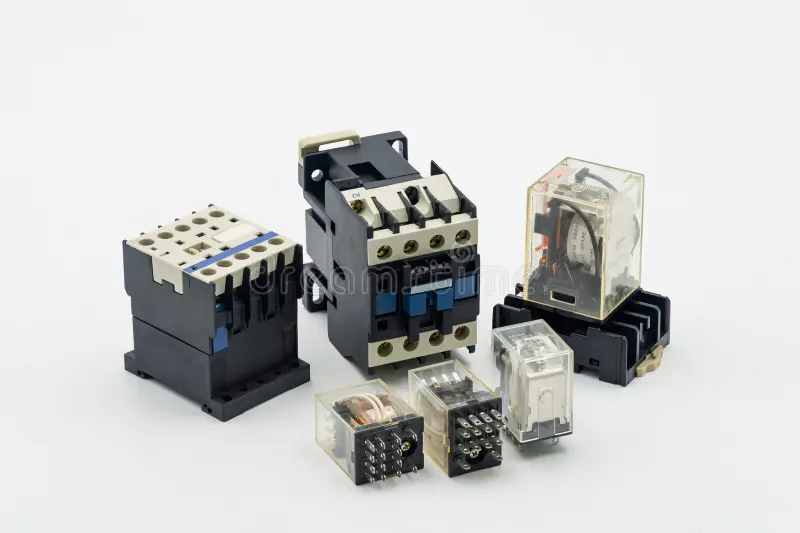
Industrial relays are electrical control devices used to automatically switch electrical circuits on or off through control signals from small currents or voltages, typically from a PLC or sensors.
When it receives a signal, the relay changes the state of its NO/NC contacts, allowing control of higher voltage and current loads without routing the load directly through the controller. This helps isolate and protect the control circuit from the load circuit.
The basic structure of an industrial relay typically consists of three main parts:
- Input circuit: Receives control signals (from PLCs, sensors, push buttons, etc.).
- Electromechanical unit: Processes the signal and determines the switching state of the relay.
- Output contacts: Perform the switching action to control loads or power circuits.
Distinguishing between industrial relays and household relays.
| Comparison criteria | Household relays | Industrial relays |
| Operating environment | Work in stable environments with little vibration and low electrical noise | Work in environments with high loads, strong electrical noise, vibration, and high temperature |
| Load capacity | Usually low current and voltage (for example 5A to 10A), mainly for small loads | Higher load capability, rated current (typically 10A to 40A or more) |
| Durability and lifespan | Moderate lifespan, designed for limited switching cycles | Designed for continuous operation with higher mechanical and electrical life |
| Protection features | Mostly basic switching functionality | Additional features such as
Arc suppression, Vibration resistance, Higher insulation standards, Overload/overcurrent protection, Auxiliary contacts for monitoring status |
Why You Must Choose the Correct Industrial Relay
In addition to fire safety risks, reduced machine lifespan, lower production efficiency, and increased maintenance costs, using the wrong industrial relays may cause:
- Propagation of high-frequency noise spikes into the control layer, causing PLC shutdowns
- Loss of electrical isolation between control circuits and power circuits
- Reduced functional safety
- Inability to maintain interlocking logic and signal duplication, leading to mechanical conflicts
Operational and Economic Impact When a Relay Fails Unexpectedly
In automated environments, relays control the on/off state of machines and optimize machine operation while protecting equipment from overload failures. Unstable relay operation can significantly affect production efficiency and costs.
Operational impacts
- Reduced equipment lifespan due to continuous or overloaded operation;
- Equipment interruptions causing sudden downtime across the production line;
- Reduced equipment availability due to frequent stops and restarts;
- Faulty relays causing incorrect machine cycles;
- Reduced product consistency due to disrupted production cycles;
Economic impacts:
- Higher maintenance and repair costs
- Higher NG (non-good) product rate, reducing profit margins
- Higher energy consumption due to repeated machine restarts
- Reduced productivity due to the domino effect where one machine stopping slows the entire production line
Functions of Relays in Industry
- Switching electrical circuits in machinery
The most important function of industrial relays is automatically switching electrical circuits accurately and safely across machinery systems. This supports smooth automation and prevents sudden circuit interruptions that may damage equipment components.
- Switching multiple voltages or currents:
With multiple contact configurations (NO/NC, DPDT, 4PDT, etc.), relays can control several separate load circuits simultaneously, each with different voltages or currents. This enables signal distribution and complex interlocking logic.
- Isolation between control signals and power circuits
Relays provide electrical isolation between low-voltage control circuits and high-voltage load circuits. Overvoltage spikes, inrush currents, electromagnetic interference, or load-side faults cannot propagate back into sensitive control circuits.
- Control signal amplification
Relays use low-power control signals to energize an internal electromagnet that switches a circuit carrying higher voltage or current. Although relays do not perform continuous amplification, they function as power amplifiers at the control level.
- Logical state switching
Industrial relays can be combined to build electromechanical logic circuits such as AND, OR, and NOT by using NO/NC contacts in series or parallel. This enables sequential control logic for machines.
Detailed Structure of Industrial Relays
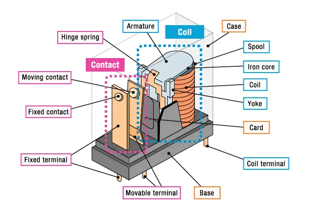
Input circuit
- Coil: A copper or aluminum coil that generates a magnetic field when current flows through it, attracting the armature in the electromagnetic unit. Common coil voltages include 12VDC, 24VDC, 110VAC, and 220VAC.
Electromagnetic unit:
- Iron core: A metal core inside the coil that strengthens the magnetic field and generates the attraction force..
- Armature: A movable metal component connected to the contacts. When the coil is energized, the magnetic field pulls the armature toward the core.
- Springs: Balances the magnetic force. When the power source is removed, the spring returns the contacts to their original position.
Output Contact System
- Normally closed contact (NC): The NC contact is closed when the relay is not energized. When the coil is energized, the armature moves and the NC contacts, breaking the circuit. .
- Normally open contact (NO): The NO contact is open when the relay is not energized. When the coil is energized, the NO contact closes, and supplies energy to the circuit.
- Changeover contacts (SPDT, DPDT, 3PDT…)
- SPDT (Single Pole Double Throw): 1 pole – 2 positions (NO & NC). Allows switching one signal to two different branches.
- DPDT (Double Pole Double Throw) 2 poles – each pole has NO & NC. Controls two independent circuits simultaneously.
- 3PDT, 4PDT…: multi-pole, allows controlling multiple independent load circuits.
Relay Socket (Socket)
A relay socket is a component used to mount relays to electrical cabinets or control panels, making wiring, maintenance, and replacement more convenient and safer.
- Materials: Typically uses heat-resistant engineering plastic, flame-retardant material (UL94-V0), socket contacts made of high-conductivity alloy.
- Pin type: Usually two types: 8-pin and 11-pin.
Suppression and protection components:
- Reverse oscillator diode: Protects the control system from sudden high reverse voltage surges when the power is cut off.
- Resistor – Varistor: Used to limit and suppress voltage spikes exceeding safe levels, protecting electronic devices from damage due to voltage overload.
Classification of industrial relays:
Classification by operating principle:
Electromagnetic relay: Electromagnetic relays use a coil to create a magnetic field that attracts moving contacts to open/close mechanical contacts, providing galvanic isolation and good overcurrent/voltage surge resistance.
- Advantages:
- Handles both AC and DC loads.
- Provides good isolation between the control circuit and the load circuit.
- Affordable and readily available.
- Disadvantages:
- Slower switching speed compared to solid-state relays.
- Mechanical wear and tear over time.
- Cracking noise during operation.
Solid-State Relay (SSR): The relay switches on/off using semiconductor components (triac/thyristor for AC, transistor/MOSFET for DC), so there are no contacts, switching is fast, quiet, and durable.
- Advantages:
- No noise during operation due to the absence of mechanical movement.
- Extremely fast switching speed.
- Higher operating life and durability.
- Disadvantages:
- Higher cost compared to electromechanical relays.
- Higher cost compared to electromechanical relays.
- May have leakage current in the “off” state.
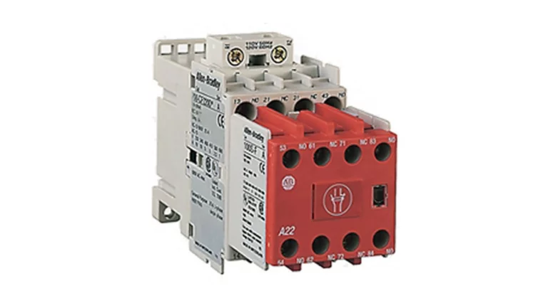
Reed Relay: Consists of two magnetic metal plates (contacts) placed in a sealed glass tube. The magnetic field (from the excitation coil or magnet) causes the plates to attract each other, closing the circuit. They are commonly used in weak signal control circuits.
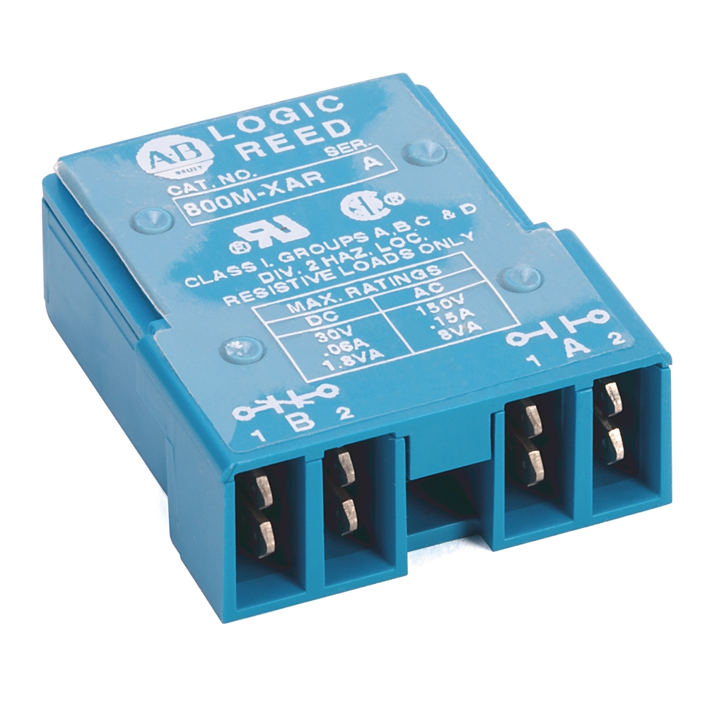
A model of Allen Bradley Reed Relay
- Advantages:
- Compact and lightweight.
- Fast circuit switching capability.
- Airtight design protects against contaminants.
- Disadvantages:
- Limited current and voltage load capacity.
- Not suitable for heavy load applications.
Classification by application:
General Purpose / Interface Relay: Used to amplify/isolate signals between PLCs, sensors, and power components; common in electrical cabinets due to easy replacement and multiple contacts.
- Advantages:
- Flexible, can control multiple loads simultaneously.
- Compact, easy to install and replace.
- Many contact types (NO/NC, SPDT, DPDT…), very common in electrical cabinets.
- Good electrical isolation between the control circuit and the load circuit.
- Disadvantages:
- Slower switching speed than solid-state relays.
- Short product lifespan due to mechanical wear.
- Small contact current, cannot withstand large loads.
Protection Relay: Protection relays monitor current/voltage/frequency/phase… and command the circuit to interrupt the current when an abnormal fault occurs to protect machinery. They are the core of protection systems in grids and industries.
- Advantages:
- Comprehensive protection: current, voltage, frequency, phase loss, phase sequence, ground fault, etc.
- Capable of self-diagnosis, fault logging, and sending information to a server.
- Disadvantages:
- Complex configuration requires a power system electrical engineer.
- Higher cost compared to other types of relays.
- Incorrect configuration can cause accidental tripping or loss of circuit protection functionality.
Timer Relay: Activates switching the current on and off in each cycle according to the set time, creating sequential logic for machinery.
- Advantages:
- Suitable for scheduling operational processes according to time in automation.
- Available in electronic, multi-mode types with display screens and wide time ranges.
- Easy to install and set up in control cabinets.
- Disadvantages:
- More complex and expensive than standard relays.
- Limited time adjustment range depending on the machine type.
Thermal Overload Relay:Protects motor overload using a bimetallic thermal element. When the bimetallic strip expands due to heat, the thermal relay cuts off the current to prevent overheating of the windings. Usually installed after the contactor.
- Advantages:
- Independent of short-term starting current (inrush), reduces accidental tripping.
- Simple, inexpensive, works well in industrial environments.
- Disadvantages:
- No short-circuit protection, only thermal overload protection.
- Less accurate than electronic protection relays.
- Sensitive to ambient temperature, may trip incorrectly if room temperature is too high.
Safety Relay:
Safety relays usually have a dual-channel circuit design and require PL/SIL certification to monitor E-stop, safety doors, photoelectric sensors, etc., and ensure safe equipment shutdown.
- Advantages:
- Dual-channel circuit, cross-fault monitoring to ensure safe shutdown.
- Extremely high reliability and continuous self-monitoring capability.
- Disadvantages:
- Higher cost than regular relays.
- Only serves for safety purposes, and does not replace PLC control.
- Requires regular maintenance due to frequent mechanical usage.
Operating Principles of Industrial Relays
Industrial relays operate on the principle of galvanic isolation between the control circuit and the load circuit. Thanks to this isolation, the control system can operate safely and stably while switching high-power devices on/off.
Operating Principles of Electromagnetic relays
The operation process takes place in three basic steps:
- Control voltage energizes the coil: Small signals from the PLC/sensor/push button are fed into the coil at levels of 12/24VDC or 110/220VAC depending on the type.
- Magnetic field generation: Current flowing through the coil creates a magnetic field in the iron core, forming a sufficiently strong attractive force to overcome the return spring force.
- Armature movement – contacts change state: The armature is attracted towards the iron core, pulling the contacts (NO/NC) to completely close/open the load circuit, separating them from the coil. Therefore, low-power control signals can safely control larger electrical loads (motors, solenoids, heaters, contactors, etc.).
Operating Principles of Solid-State Relay – SSR
Solid-state relays perform similar switching functions but without moving mechanical parts. Instead of electromagnetic-mechanical force, SSRs use semiconductor components (triacs/thyristors/MOSFETs) to open/close the load circuit.
Common Faults when Using Industrial Relays:
Contact burnout – due to arcing when switching on/off inductive loads:
- Cause: When switching on/off inductive loads (motors, solenoids, coils), magnetic field energy creates an arc at the contacts; if not properly extinguished or if the wrong material/contact rating is selected, the arc will corrode and blacken the contact surface.
- Consequences: Increased contact resistance and heat generation, causing the contacts to solder together. At this point, the load does not switch off, creating a risk of equipment damage/arc spread.
- Prevention: Choose the correct relay rating and load type (resistive/inductive), prioritizing industrial relays from manufacturers like Rockwell/Phoenix for high-cycle and high-noise environments.
Coil burnout due to incorrect voltage (overvoltage, AC/DC error)
- Causes: Incorrect voltage supply, relay installed in a location with poor heat dissipation; lack of protective components (diode/MOV) increasing reverse surges to the coil.
- Consequences: Overheating of the coil, melting of the insulation paint, broken windings; potentially leading to PLC/driver output failure if a short circuit occurs.
- Prevention: Verify the coil voltage (12/24VDC, 110/220VAC) to ensure correct type. Provide proper ventilation/heat dissipation; Use reverse polarity protection diodes for the DC winding and MOV/snubber for the AC winding to reduce reverse pulses.
Relay vibration due to noise, weak winding, and fluctuating control power supply
- Causes: Control power supply fluctuating around the pickup/dropout threshold, noise from the inverter/VFD, control wiring mixed with power wiring, windings not at the rated voltage; lack of suppression resulting in high dv/dt and di/dt causing relay vibration
- Consequences: Continuous contact bouncing, leading to rapid wear and heat generation; incorrect control logic, causing operational chain errors.
- Prevention: Ensure winding voltage ≥ V_pickup and a safe margin relative to V_dropout (according to IEC 61810’s concept of all-or-nothing/pickup–dropout), and separate control and power wiring.
Non-returning contacts – due to mechanical jamming or dirt/oxidation
- Causes: Dirt, corrosive substances; long-term arcing creating slag; mechanical vibration causing misalignment of the connecting rod; lack of regular maintenance; selection of contact material unsuitable for the load type.
- Consequences: Contact jamming in the open/closed state → loss of load control (not switching on/off as command), safety risk and line damage.
- Prevention: Choose industrial relays with suitable contact materials (AgNi, AgSnO₂…) and correct load rating; adhere to maintenance schedules.
Why should you choose Rockwell Automation’s Allen Bradley Relays?
- Stable operation & high reliability: Meets stringent international standards such as EU standards, IEC standards, and EN 50205 standards; suitable for heavy industrial environments;
- Diverse contact configurations: Multiple contact options to suit all machine needs, with gold-plated contact technology and optimized small signal design to reduce interference and increase relay lifespan;
- Diverse product range: From general-purpose to timing, solid-state, and interposing;
- Optimized for Rockwell PLC products: Reduced load, reduced leakage, increased I/O stability;
- High durability and uptime, optimized for factories and production lines operating 24/7;
- Easy lifecycle management with Product Lifecycle Status system: Easy replacement and maintenance planning.
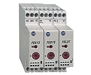
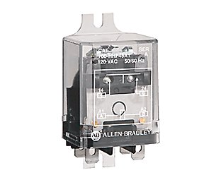
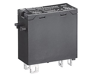
Some models of Allen Bradley – Rockwell Automation industrial relays
How to Read Product Codes and Choose Allen Bradley Relays from Rockwell Automation
Typically, a complete product code for the Allen Bradley relay product line is as follows:
[700] – [HA] – [X2] – [A2] – [4L]
[700] – [Product Line] – [Contact Configuration] – [Coil Voltage Code] – [Expansion Options]
In this code, “700” represents the product code for the Allen Bradley 400 series relay.
The first two letters (HA, HB, HL, SH, HP…): Relay Series and Type
Each letter identifies the relay type, according to the following table:
| Code | Type | Characteristics |
| HA | General‑purpose, Tube Base | Features split contacts and gold plating, suitable for small signal loads and control circuits requiring high sensitivity. |
| HB | General‑purpose Blade Base | Easy and quick wiring, no round pin socket required.
Suitable for control panels that Industrial applications require quick replacement. |
| HC / HF / HJ | General-purpose expansion | HC – Compact square relay, suitable for tight spaces.
Easily uses shared sockets with HL and other series. HF – Compact plug-in relay, transparent for contact observation. HJ – Magnetic relay that holds state without maintaining current through the coil, saving energy. |
| HL | Interposing – Intermediate relay | For applications between PLC and load (valves, coil contactors, etc.).
Features “leakage-current suppression”, particularly useful when used with PLC transistor outputs, helping to avoid false triggering due to leakage current. Available with push-in terminal, cage clamp, or screw terminal options. |
| HK | Interposing plug-in | Similar to the HL group but uses flat pins.
Easily uses shared DPDT or 4PDT sockets, standardizing components. |
| HP / HPS | Safety / PCB | Features forced contacts, snap-in type pins, and is used for safety applications.
Includes force-guided/mechanically-linked safety mechanism according to EN 50205 standard. Used in circuits: E-STOP, door interlocks, contact monitoring circuits. |
| FS/FE/HR | Time Relays | FS: DIN rail-mounted time relay series, slim design for space saving.
FE: Basic electronic time relay series. HR: Dial-type time relay series. |
| SH / SK | Solid-State | Contactless relay, entirely solid-state switching.
The 700-SH version can handle high continuous current loads and has status LEDs. |
The next digits: Number of poles & contact type
The numbers in the code usually indicate:
- The first digit indicates the contact type: SPDT / DPDT / 3PDT…
- The second digit indicates the relay type: 1 pole / 2 poles / 3 poles / 4 poles
| Code | Meaning |
| 32 | DPDT – 2 pole switching |
| 33 | DPDT – 3 pole switching |
| 22 | SPDT – 1 pole switching |
| 44 | 4PDT – 4 pole switching |
| X | Special multi-pole configuration |
Last digits: Coil voltage code
This is the most important part when selecting a relay. Each relay model has a unique coil code, used to identify the coil’s control voltage. In which:
- The first letter indicates the nature of the coil:
- A (for AC power),
- D (for DC power, with integrated noise suppression diode)
- Z (for DC power, without integrated noise suppression diode)
- E (for electronic DC power, with integrated noise suppression diode)
- The number after indicates the voltage value (12, 24, 48, …)
Common coil codes in the 700 series include:
- A1: 120 VAC
- A2: 240 VAC
- Z24/D24: 24 VDC
- D12: 12 VDC
- E48: 48 VDC
Extension suffixes
The end of the code usually consists of letters indicating extended features of some Allen Bradley relay series, including:
| Code | Meaning | Characteristics |
| L | Includes LED status indicator | Quick status monitoring
Easy signal checking from PLC Convenient maintenance In multi-device cabinet |
| S | Includes noise suppression circuit (MOV, diode) | PLC output protection
Reduces arcing at contacts Reduces relay vibration |
| K | Plug-in terminal blade type | These types of relays allow for quick wiring, easy relay replacement, and are suitable for electrical cabinets requiring frequent maintenance. |
| V | With varistor resistor | Reduces voltage surges when the coil is released
Reduces interference spreading to the PLC Protects equipment lifespan |
| R | Bistable relay type | Allows the relay to maintain a state without maintaining current in the coil, helping to:
– Save energy – Maintain state when the PLC loses power – Maintain interlocking logic in the system |
| X | Special code for contacts or extended structure | Special contacts
Custom multi-pole structure |
Servo Dynamics – Official Distributor of Rockwell Automation in Vietnam
Servo Dynamics is one of the official distributors of Rockwell Automation in Vietnam, specializing in providing comprehensive industrial automation solutions. With years of experience and a team of experienced technicians, Servo Dynamics has affirmed its position in the market and become a trusted partner of many businesses.
Why choose Servo Dynamics?
Genuine Products: Servo is committed to providing genuine Rockwell Automation products, ensuring high quality and reliability.
Comprehensive Solutions: From consultation, design, equipment supply, installation, operation, and maintenance, Servo Dynamics provides a complete solution for automation projects.
Professional Team: Servo’s technical team is well-trained and has many years of experience in the automation field, ready to support customers anytime, anywhere.

