Tiếng Việt
Consulting, Industrial Automation, News
CIP Safety Protocol: Safety and Standards for Automation Systems

What is CIP Safety?
Industrial communication networks have revolutionized automation, enabling the distribution of processing, sensing, and actuation mechanisms to every corner of a system. The CIP Safety™ protocol was created to bring similar benefits to functional safety applications, a mandatory requirement for modern production lines.
Definition of the CIP Safety Protocol
CIP Safety is an extension of the Common Industrial Protocol (CIP), designed to transmit safety data with high integrity over CIP-based networks such as EtherNet/IP™.
This protocol has been certified by independent certification bodies, notably TÜV Rheinland, to meet functional safety standards, allowing it to be used in applications requiring the highest Safety Integrity Level (SIL).
The Role of CIP Safety in EtherNet/IP Networks and Industrial Systems
CIP Safety’s core role is to provide a safety solution that is media-independent.
- Replacing Hardwired Safety Systems: CIP Safety eliminates the limitations of traditional hardwired safety systems (using relays, difficult to change, high cost) by providing a network-based safety solution. This reduces wiring costs, increases flexibility, and improves maintenance capabilities.
- Safe Data Routing: CIP Safety allows for continuous safe data routing, creating end-to-end safety chains across multiple links and different network layers.
- Seamless Integration: By extending the CIP application layer, it allows safety devices and standard devices to coexist on the same EtherNet/IP network.
CIP vs. CIP Safety – What is the Difference?
The key difference lies at the Application Layer:
| Characteristic | CIP (Standard) | CIP Safety |
|---|---|---|
| Primary Function | Transmits standard control and informational data. | Transmits safety data with high integrity. |
| Network Layer | Uses standard network services. | Adds CIP Safety Validator function and protection mechanisms. |
| Hardware | Requires integrity of lower layers (Ethernet, cable). | Allows the use of single-channel, non-redundant communication hardware (Black Channel principle). |
| Reliability | Relies on standard network reliability. | Integrates robust error detection mechanisms (CRC, Time Stamp, PID). |
How CIP Safety Works
The operational mechanism of CIP Safety revolves around the “Black Channel” principle and various error detection measures to ensure safety data is not compromised during transmission.
The “Black Channel” Protection Principle
The Black Channel principle is the foundation of CIP Safety, allowing safety data to be transmitted over standard communication channels (like Ethernet) without relying on the integrity of that channel.
- Function: The entire safety function (data validation, error detection) is located at the Application Layer on the end devices (Safety Originator and Safety Target).
- Independence: Intermediary devices such as switches, routers, or standard network cables only act as a “black channel”—they transmit the safety data but do not need to check or guarantee its safety integrity. If a channel error occurs, the end device will detect it and transition to a safe state.
How CIP Safety Detects and Handles Errors
CIP Safety uses multiple diverse measures to ensure integrity, overcoming errors that may occur at the physical or communication layers:
| Measure | Purpose | Mechanism |
|---|---|---|
| Safety CRC (Cyclic Redundancy Code) | Detects corrupted data errors (e.g., bit stuff errors, fragmentation errors). | Uses 16-bit and 24-bit Safety CRCs to check the end-to-end integrity of the packet. Ensures error detection capability up to a Hamming distance of 4. |
| Time Stamp & Watchdog | Detects latency, packet loss, and re-use of old data. | The producing device (Producer) uses a Ping/Offset mechanism to determine network latency. A time stamp is sent with the data. The consuming device (Consumer) rejects data if its age exceeds the maximum allowed limit (watchdog timeout). |
| PID (Production Identifier) | Ensures the message reaches the correct consuming device. | A unique identifier encoded in the packet, derived from the electronic key, device serial number, and connection serial number. Prevents forgery or misrouting. |
| Safety Signature | Prevents configuration errors. | A set of safety configuration parameters (Safety Network Number – SNN, actions, device data) is generated and checked upon device startup. If the signature does not match, the device will not operate. |
Safe Communication Architecture: Originator – Target – Connection
CIP Safety communication is established through Safety Connections using the Safety_Open service (an extension of EtherNet/IP’s Forward_Open).
- Originator (Producer): Typically a safety input device (Safety I/O) or a safety controller that generates safe data.
- Target (Consumer): Typically a safety controller or a safety actuator (Safety Drive, Light Curtain) that receives and executes actions based on the safe data.
- Connection: Can be Unicast (one Producer to one Consumer) or Multicast (one Producer to many Consumers), using connection-based communication to enhance noise immunity and reliability.
CIP Safety over EtherNet/IP and Related Protocols
CIP Safety is designed to operate on the EtherNet/IP platform (the most common industrial protocol in North America and the foundation for major manufacturers like Rockwell Automation).
EtherNet/IP provides the basic data link and network layers, while CIP Safety provides the safety application layer. This separation allows CIP Safety to leverage standard Ethernet infrastructure (cables, switches, routers) while maintaining the highest level of safety.
Advantages of CIP Safety in Automation
CIP Safety provides significant benefits, helping manufacturers achieve a balance between production efficiency and safety standards.
Reliability & Redundancy
- Robust Error Detection: Thanks to redundant protection mechanisms (CRC, Time Stamp, PID), the protocol can detect most communication errors with high accuracy.
- Tolerance to Noise: The protocol allows packet re-transmission as long as they are received within the expected timeframe (Time Stamp), helping the connection remain operational even with minor network noise, thereby increasing system availability.
Cost Optimization and Simplified Integration
- Reduced Wiring Costs: Replaces complex relay and wiring systems with standard Ethernet cables.
- Use of Standard Hardware: Maximizes the use of existing EtherNet/IP network infrastructure, allowing the use of conventional switches and routers (Black Channel).
- Centralized Configuration: The safety device configuration process (Safety Signature) is performed centrally using tools, simplifying deployment and maintenance.
Flexibility in System Expansion
- Distributed Architecture: Allows users to create local safety cells with fast response times, while simultaneously routing safe data between cells to create large and complex safety applications.
- Multi-Link Expansion: The ability for multi-link routing through routers enables seamless connection to remote areas or different network segments, meeting future expansion needs.
What Devices Does CIP Safety Support?
CIP Safety is an open standard supported by hundreds of vendors, primarily focused on specialized safety devices.
Safety Controllers / Safety PLCs
These are the brains of the safety system, responsible for processing safety logic.
- Allen-Bradley / Rockwell Automation: GuardLogix Controllers.
- Omron: NX102 Series.
- Siemens: PLCs with integrated CIP Safety (usually via a communication module).
Safety I/O, Safety Remote I/O, Safety Modules
Certified I/O modules for connecting safety field devices.
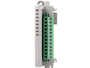
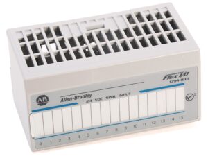
- Safety Remote I/O: Distributed modules (e.g., Allen-Bradley’s POINT I/O) allow for remote safe data acquisition over the EtherNet/IP network.
- Safety Module: Functional modules integrated into PLCs or Drives.
Safety Encoders, Safety Scanners, Light Curtains
Specialized safety input field devices:
- Safety Encoder: Provides safe position and speed feedback (Safe Speed, Safe Direction).
- Safety Scanner & Light Curtain: Area protection devices that send safety status via CIP Safety.
- E-stop (Emergency Stop Button): Connected via Safety I/O or a dedicated E-stop module.
Safety Drives
Drives with integrated safety functions (Safe Torque Off – STO, Safe Stop 1 – SS1, Safe Speed Monitor – SSM, etc.), receiving safety commands directly via CIP Safety.
- Rockwell Automation: PowerFlex 525/527/755, Kinetix 5300/5500/5700.
Practical Applications of CIP Safety in Industry
CIP Safety is widely deployed across industries requiring high safety standards.
Industrial Robots
- Collaborative Robot Systems (CoBot): CIP Safety allows for safe monitoring of robot speed, position, and work zones. If an operator enters a restricted area, CIP Safety immediately triggers the safe stop function.
- Integration: Major robot manufacturers like Fanuc, ABB, and KUKA offer CIP Safety interfaces for easy connection to other Safety Controllers.
Production Lines & Packaging
- Access Control: Uses Light Curtains and Scanners to protect hazardous access points.
- Safe Hydraulic/Pneumatic Control: Safety I/O modules from brands like Festo and SMC are used to control safety valves.
Conveyor Systems and AGVs/AMRs
- Conveyor Speed Monitoring: Safety Encoders transmit safe speed information.
- AGV/AMR Collision Control: Safety scanners on automated vehicles send safe zone data via CIP Safety, enabling emergency stops upon detecting obstacles or personnel.
Area Safety Systems
This is the most basic application, where CIP Safety connects distributed safety input devices to a centralized Safety Controller, significantly reducing cabling costs and increasing fault diagnostics capability.
CIP Safety Integration by Brand
Allen-Bradley / Rockwell Automation
One of the leading developers of EtherNet/IP and CIP Safety.
- GuardLogix CIP Safety: Integrated safety controller, allowing standard control logic and safety logic to be processed on the same platform.
- PowerFlex 525/527/755: Drives with integrated safety functions (such as STO, SS1), controlled via CIP Safety over EtherNet/IP.
- Kinetix 5300/5500/5700: Servo Drives with advanced safety functions, commonly used in complex robot and machinery applications.
Omron CIP Safety
Omron uses CIP Safety in its integrated automation systems.
- NX102, NA0 series: PLCs and HMIs that support CIP Safety, allowing seamless integration of Omron safety devices.
- Network Configurator for CIP Safety: Dedicated Omron software tools for configuring the safety network.
ABB CIP Safety
- ABB Robots: ABB robots can be equipped with a CIP Safety Adapter to communicate with other Safety Controllers.
- CIP Safety Adapter – IP Mismatch Issues: A common configuration error when integrating ABB Robots is an IP Mismatch between the robot controller and the configuration in the Safety Controller.
Fanuc CIP Safety
- Setting up CIP Safety for Fanuc Robots: Involves configuring Safety Parameters in the Robot Controller and establishing the Safety Connection in the PLC.
- Common Errors: Comm Error 1 1: A frequent communication error, often related to mismatched PID, expired Time Stamp, or SNN configuration errors.
CIP Safety Configuration Tools and Software
The CIP Safety configuration process is a critical step and must be performed accurately.
Network Configurator for CIP Safety
These specialized software tools (e.g., from Rockwell Automation, Omron, Belden, HMS) are used to:
- Set up safety parameters (Safety Parameters).
- Assign the Safety Network Number (SNN).
- Establish Safety Connections using the Safety_Open service (Type 1: Simultaneous configuration and connection, or Type 2: Pre-configuration).
EDS/EDS-A, IO-Link Safety Configuration
- EDS/EDS-A Files: Electronic Data Sheet/A (Safety) files are used by the configuration tool to identify and understand the capabilities of the CIP Safety device.
- IO-Link Safety: A newer extension of CIP Safety technology, allowing safe data transmission to simple, compact field sensors/devices.
Configuration Deployment and Protection Measures
To ensure configuration integrity, CIP Safety provides the following protection measures:
- Safety Network Number (SNN): A unique network identifier used along with the local device address to ensure each device is uniquely identified.
- Password Protection: Prevents device reconfiguration without a valid password.
- Configuration Ownership: Specifies and enforces which device/tool is authorized to configure the safety device.
- Configuration Lock: Provides a mechanism to confirm that all devices have been verified and tested before operation.
Common CIP Safety Errors and Troubleshooting
CIP Safety Comm Error 1 1
This error is usually a general notification that the safety connection has been lost.
- Common Causes: Mismatched PID (due to device replacement), expired Time Stamp (due to network being too slow or watchdog configuration being too short), or SNN configuration error.
- Solution: Recheck PID, SNN, and adjust the Watchdog/Timeout period.
CIP Safety IP Address Mismatch
A configuration error where the IP address of the Robot or device does not match the configuration set up in the Safety Controller.
- Solution: Ensure the physical IP address of the device matches exactly the IP address configured in the Safety Controller and network configuration tool.
Loss of Originator – Target Connection
- Causes: Physical error (cable, switch), routing configuration error, or intermediate device (router) failure.
- Solution: Use network diagnostic tools (ping, traceroute) to check basic connectivity, then recheck the Safety_Open connection parameters.
CRC Configuration Error, Watchdog Timeout
- Causes: Excessive network noise causing incorrect CRC, or the network cycle time (RPI) being too long compared to the watchdog time.
- Solution: Improve network cable quality, reduce network load, or increase the watchdog/timeout period (within the limits allowed by the application).
CIP Safety Comparison with Other Safety Standards
CIP Safety is not the only safety standard on the market. Key competitors include PROFIsafe and FSoE.
CIP Safety vs. PROFIsafe
| Characteristic | CIP Safety (EtherNet/IP) | PROFIsafe (PROFINET/PROFIBUS) |
|---|---|---|
| Network Platform | EtherNet/IP, standard Ethernet/TCP/IP. | PROFINET (Ethernet), PROFIBUS (Fieldbus). |
| Principle | Black Channel. | Black Channel. |
| Market Segment | Popular in North America, strongly supported by Rockwell Automation, Omron. | Popular in Europe, strongly supported by Siemens, Phoenix Contact. |
| Flexibility | Highly flexible, easy to route over IP networks. | Flexible, but primarily focused on the Siemens/Profinet ecosystem. |
CIP Safety vs. FSoE (Functional Safety over EtherCAT)
| Characteristic | CIP Safety | FSoE (Functional Safety over EtherCAT) |
|---|---|---|
| Network Platform | EtherNet/IP (TCP/IP). | EtherCAT (High-performance Ethernet-based communication protocol). |
| Speed/Performance | High speed, but dependent on IP network load. | Extremely high speed, prioritized for fast motion control applications. |
| Independence | Media-independent. | Highly dependent on the EtherCAT structure. |
When to Choose Which Standard?
- Choose CIP Safety: If your system already uses or plans to use EtherNet/IP, or if the system requires deep integration with devices from Rockwell Automation (Allen-Bradley) and ODVA standard vendors. It is an excellent choice for applications requiring flexibility and routing capabilities.
- Choose PROFIsafe: If your system uses PROFINET/PROFIBUS and the Siemens/European ecosystem.
- Choose FSoE: If your application requires extremely high performance, tight synchronization, and complex motion control (e.g., high-speed packaging machines, delta robots).
Servo Dynamics Engineering: Value-add Distributor of Rockwell Automation in Vietnam
Servo Dynamics Engineering is the official Value-add Distributor for Rockwell Automation in Vietnam, specializing in providing comprehensive automation solutions, including functional safety systems utilizing the CIP Safety protocol. We are committed to supplying genuine products, in-depth technical support services, and optimal integration solutions for your system.
What is VFD? VFD stands for Variable Frequency Drive. It’s basically an electronic device that [...]
In the era of Industry 4.0, Human-Machine Interface (HMI) plays a crucial role in optimizing [...]
In modern manufacturing environments, the ability to quickly connect and transfer data between devices is [...] Discover Rockwell Automation Products
Learn More

Variable frequency drive (VFD) explained
May

What is HMI? How It Works and Industrial Applications
Feb

What is an Industrial Communication Network? Types and Applications
Mar