Tiếng Việt
Technical Support
PowerFlex 755TS Forward and Reverse Bias Check Frame 1-7

Summary
PowerFlex 755TS Forward and Reverse Bias Check Frame 1-7
Question
- How are the forward and reverse biased SCR/diode tests performed on the major power components on the PowerFlex 755TS Frame 1-7A?
- How should a SCR or Diode check be performed to check the health of the SCR’s Diodes, or IGBT’s the PowerFlex 755TS Frame 1-7A?
Environment
PowerFlex 755TS Frame 1-7A
Answer
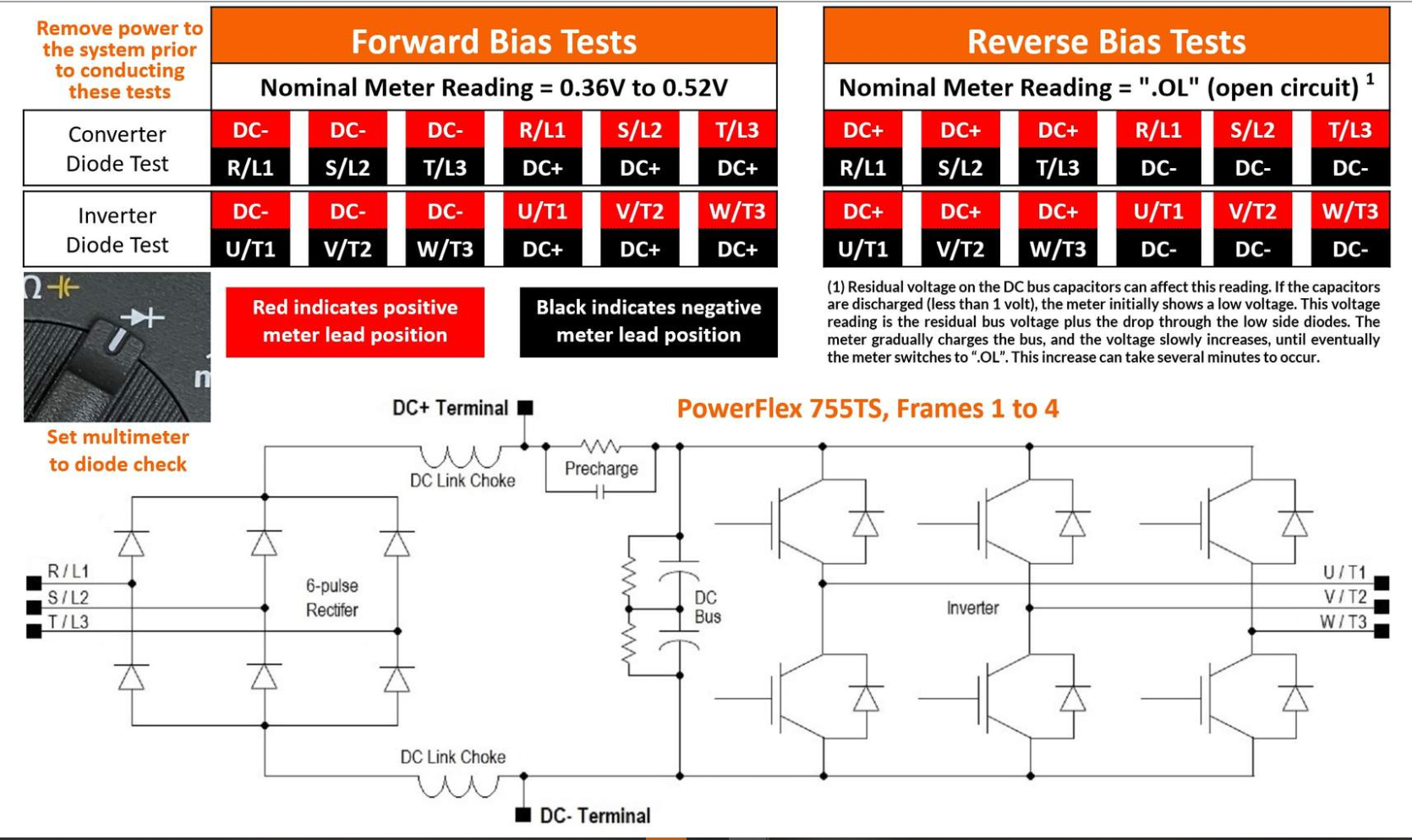
PowerFlex 755TS Frame 1 to Frame 4 drives use a standard three-phase rectifier containing six diodes.
Follow this procedure to complete the forward and reverse bias tests:
- Remove power to the drive. Lock out and tag out energy sources as required
- Ensure meter leads are plugged in correctly and set the multimeter to diode check mode
- Touch the Positive probe (RED) of the meter to the DC- terminal of the drive, then touch the Negative probe (BLACK) to each input and output terminal (L1, L2, L3, T1, T2, T3). The meter should display a value between 0.36 V and 0.52 V
- Touch the Negative probe (BLACK) of the meter to the DC+ terminal of the drive, then touch the Positive probe (RED) to each input and output terminal (L1, L2, L3, T1, T2, T3). The meter should display a value between 0.36 V and 0.52 V
- Touch the Positive probe (RED) of the meter to the DC+ terminal of the drive, then touch the Negative probe (BLACK) to each input and output terminal (L1, L2, L3, T1, T2, T3). The meter should display “.OL,” indicating an open circuit condition. The reading may take a moment to stabilize based on the residual bus voltage and the drive size.
- Touch the Negative probe (BLACK) of the meter to the DC- terminal of the drive, then touch the Positive probe (RED) to each input and output terminal (L1, L2, L3, T1, T2, T3). The meter should display “.OL,” indicating an open circuit condition. The reading may take a moment to stabilize based on the residual bus voltage and the drive size.
If the readings are different than indicated in the previous steps, then the drive should be returned to Rockwell Automation for analysis and repair.
See Below:
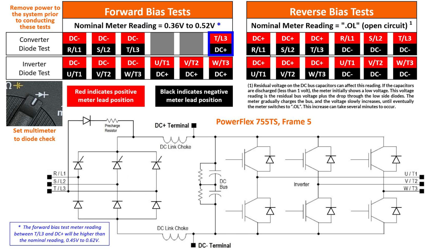
PowerFlex 755TS frame 5 drives use silicon controlled rectifiers (SCR) for the upper section of the converter, and diodes for the lower section. There is an added series resistor and diode connected between the T/L3 and DC+ terminals for precharge.
Follow this procedure to complete the forward and reverse bias tests:
- Remove power to the drive. Lock out and tag out energy sources as required
- Ensure meter leads are plugged in correctly and set the multimeter to diode check mode
- Touch the Positive probe (RED) of the meter to the DC- terminal of the drive, then touch the Negative probe (BLACK) to each input and output terminal (L1, L2, L3, T1, T2, T3). The meter should display a value between 0.36 V and 0.52 V
- Touch the Negative probe (BLACK) of the meter to the DC+ terminal of the drive, then touch the Positive probe (RED) to the output terminals (T1, T2, T3). The meter should display a value between 0.36 V and 0.52 V
- Also, touch the Negative probe (BLACK) of the meter to the DC+ terminal of the drive, then touch the Positive probe (RED) to the T/L3 terminal. (The forward bias test meter reading between T/L3 and the DC+ will be higher than the nominal reading of 0.45 to 0.62V because of the Precharge circuit). Refer to the schematic diagram below.
- Touch the Positive probe (RED) of the meter to the DC+ terminal of the drive, then touch the Negative probe (BLACK) to each input and output terminal (L1, L2, L3, T1, T2, T3). The meter should display “.OL,” indicating an open circuit condition. The reading may take a moment to stabilize based on the residual bus voltage and the drive size
- Touch the Negative probe (BLACK) of the meter to the DC- terminal of the drive, then touch the Positive probe (RED) to each input and output terminal (L1, L2, L3, T1, T2, T3). The meter should display “.OL,” indicating an open circuit condition. The reading may take a moment to stabilize based on the residual bus voltage and the drive size.
If the readings are different than indicated above, then the drive should be returned to Rockwell Automation for analysis and repair.
See Below:
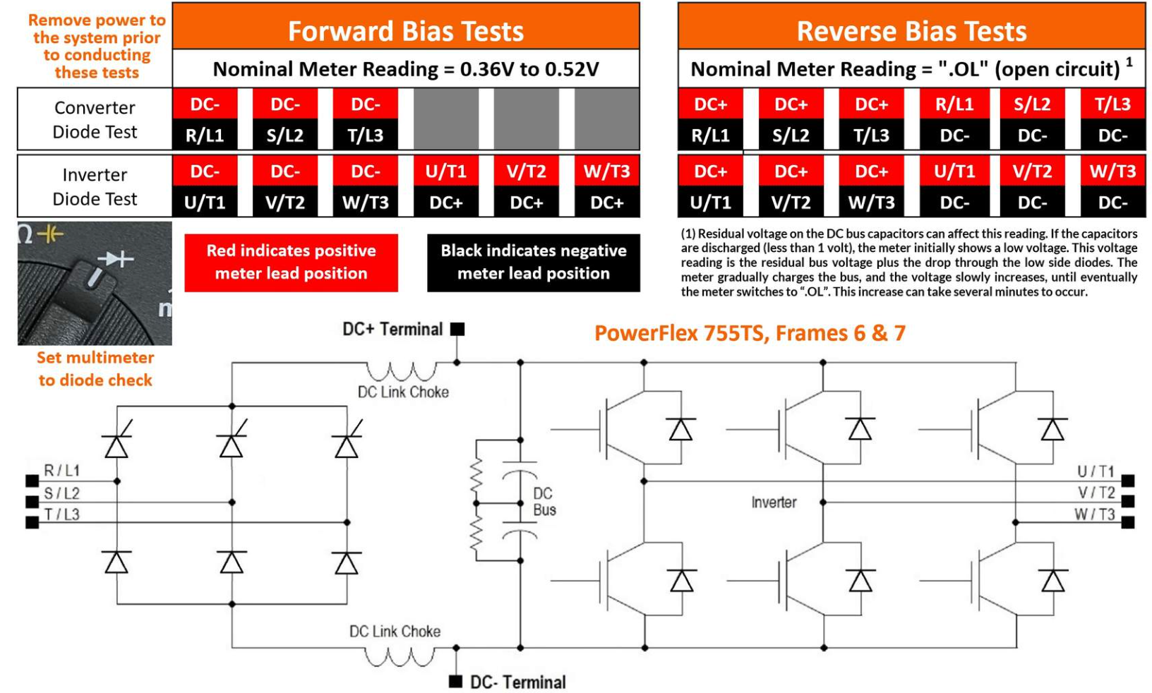
PowerFlex 755TS frame 6, 7 and 7A drives use silicon-controlled rectifiers (SCR) for the upper section of the converter and diodes for the lower section. Follow this procedure to complete the forward and reverse bias tests:
- Remove power to the drive. Lock out and tag out energy sources as required
- Ensure meter leads are plugged in correctly and set the multimeter to diode check mode
- Touch the Positive probe (RED) of the meter to the DC- terminal of the drive, then touch the Negative probe (BLACK) to each input and output terminal (L1, L2, L3, T1, T2, T3). The meter should display a value between 0.36 V and 0.52 V
- Touch the Negative probe (BLACK) of the meter to the DC+ terminal of the drive, then touch the Positive probe (RED) to each output terminal (T1, T2, T3). The meter should display a value between 0.36 V and 0.52 V
- Touch the Positive probe (RED) of the meter to the DC+ terminal of the drive, then touch the Negative probe (BLACK) to each input and output terminal (L1, L2, L3, T1, T2, T3). The meter should display “.OL,” indicating an open circuit condition. The reading may take a moment to stabilize based on the residual bus voltage and the drive size. Larger drives can take many minutes to stabilize
- Touch the Negative probe (BLACK) of the meter to the DC- terminal of the drive, then touch the Positive probe (RED) to each input and output terminal (L1, L2, L3, T1, T2, T3). Meter should display “.OL,” indicating an open circuit condition. The reading may take a moment to stabilize based on the residual bus voltage and the drive size. Larger drives can take many minutes to stabilize.
If the readings are different than indicated in the procedure, then the drive should be returned to Rockwell Automation for analysis and repair.
See Below:
Also Reference:
PowerFlex 755TS Products with TotalFORCE Control, Hardware Service , Publication 750-TG101 for locations on the drive and renewal parts that may be available.
For other Rockwell Automation/Allen Bradley PWM drives see QA14332 – PowerFlex PWM AC Drives: SCR/Diode and IGBT Test
Source: Rockwell Automation’s Technote database.